It is of vital importance, before attempting to operate your engine, to read the general 'SAFETY INSTRUCTIONS AND WARNINGS' section on pages 2-4 of this booklet and to strictly adhere to the advice contained therein. Also, please study the entire contents of this instruction manual, so as to familiarize yourself with the controls and other features of the engine. Keep these instructions in a safe place so that you may readily refer to them whenever necessary.
SAFETY INSTRUCTIONS AND WARNINGS ABOUT YOUR O.S. ENGINE WARNINGS • Never touch, or allow any object to come into contact with, the rotating propeller and do not crouch over the engine when it is running. Remember that your engine is not a " toy ", but a highly efficient internal-combustion machine whose power is capable of harming you, or others, if it is misused or abused. As owner, you, alone, are responsible for the safe operation of your engine, so act with discretion and care at all times.
NOTES • Take care that the glow plug clip or battery leads do not come into contact with the propeller. Also check the linkage to the throttle arm. A disconnected linkage could also foul the propeller. • After starting the engine, carry out any needle-valve readjustments from a safe position behind the rotating propeller. Stop the engine before attempting to make other adjustments to the carburettor.
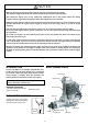
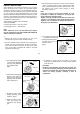
RELOCATION OF CARBURETOR CONTROLS CHOKE VALVE The needle-valve and throttle lever locations are interchangeable by reversing the carburetor. This can be done as follows: Remove the carburetor carefully by unscrewing the two screws which secure both carburetor and choke valve. (See Photo 1.) If the carburetor remains difficult to remove, slightly loosen the two screws which secure the intake pipe to the cylinder head.
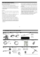
EXHAUST HEADER PIPE & SILENCER THROTTLE LINKAGE Install these in the following sequence. Screw the header pipe into the cylinder head until it " bottoms ", then unscrew sufficiently to achieve the desired exhaust angle and tighten the locknut securely with a 17mm wrench. Screw the silencer onto the outer end of the header pipe and tighten the other locknut.
Since the FS-120S-E is intended to be started with an electric starter, the addition of a spinner assembly for centering the starter sleeve is desirable. Special propeller locknut sets are available for use with spinners. Use a good quality well balanced spinner, enclosing the propeller boss. Make sure that it is of precision-made and sturdy construction so that the spinner shell cannot loosen when the starter is used. Make sure the spinner notches do not interfere the propeller.
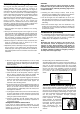
CARBURETTOR Throttle Stop Screw Three adjustable controls are provided on this carburetor. • The Needle Valve This is used to establish the fuel/air mixture strength required for full power when the throttle is fully open. • The Mixture Control Valve (Mixture Control Screw) This is used to establish the mixture strength required for steady idling and a smooth transition to medium speeds.
WARNING: When ground running the engine, avoid dusty or sandy locations. If dust or grit is drawn into the engine, this can have a ruinous effect, drastically shortening engine life in a matter of minutes. RUNNING-IN ("Breaking-in") For long life and peak performance, every engine needs special treatment when new, known as "running-in" or "breaking-in".
3. The standard valve clearance, on both inlet and exhaust valves, is between 0.04mm and 0.10mm(0.0015-0.004 inch), measured between valve stem and rocker arm. Use the 0.04mm and 0.10mm feeler gauges to check clearances. (See Fig.1.) VALVE ADJUSTING Valve clearances are correctly set before any O.S. engine leaves the factory and, in normal use, will seldom require abjustment.
CARE AND MAINTENANCE To ensure that you obtain long life and peak performance from your engine, observe the following. 4. Clean the exterior of the engine with a clean cotton cloth.If this is not done, oil and dirt will burn onto the outside of the engine each time it is run and the engine will soon become discolored. 1. Avoid running the engine under dusty conditions. If necessary, lay a sheet of plywood or hard-board in front and under the nose of the model when starting the engine. 5.
C.M2.6X7 33 24 25 32 17 16 14 13 19 18 C.M4.0X10 10 C.M3X8 11 9 Type of screw 1 C...Cap Screw M...Oval Fillister-Head Screw F...Flat Head Screw N...Round Head Screw S...Set Screw 32-1 8 5 21 20 5-4 5-3 5-2 5-1 12 22 23 24 31 30 28-2 29 26 28 28-1 28-2 27 15 6-1 7 6-2 6-3 6-4 6 3 (C.M3.5X12) 4-1 4 4-2 3-2 3-1 C.M3.5X20 2 C.M2.6X15 EXPLODED VIEW 20 PARTS LIST No. Code No.
CARBURETOR EXPLODED VIEWS & PARTS LIST 1 Type of screw 1-1 S.3X3 C...Cap Screw M...Oval Fillister-Head Screw F...Flat Head Screw N...Round Head Screw S...Set Screw 2 3 6 7 3-1 4 8 9 10 9-4 9-1 9-5 5 11 No. 1 1-1 2 3 3-1 4 5 6 7 8 9 9-1 9-2 9-3 9-4 9-5 10 11 9-2 9-3 S.3X3 N.+M3X22 Description Throttle Lever Assembly Set Screw Carburetor Rotor Mixture Control Valve Assembly "O" Ring (2pcs.
MEMO LL L I TY PRECISION & P ERF QUA ED OR E ANC TA ISH ING NC E ES BL M UNEQ UA 24 L CEL THE STAN ARDS OF EX D E 6-15 3-Chome Imagawa Higashisumiyoshi-ku Osaka 546-0003, Japan TEL. (06) 6702-0225 FAX. (06) 6704-2722 C Copyright 2003 by O.S.Engines Mfg. Co., Ltd. All rights reserved. Printed in Japan. URL : http://www.os-engines.co.