MODEL HYBRID-35 FREESTANDING & FIREPLACE INSERT OWNER’S MANUAL • • • • Warning: If your appliance is not properly installed, a house fire may result. For your safety, follow the installation directions. Contact local building or fire officials about restrictions and installation inspection requirements in your area. Please read this entire manual before installation and use of this pellet fuel-burning room heater.
INTRODUCTION Thank you for purchasing the HYBRID-35 pellet stove & insert. You are now prepared to burn wood in the most efficient, convenient way possible. To achieve the safest, most efficient and most enjoyable performance from your stove, you must do three things: 1) Install it properly; 2) Operate it correctly; and 3) Maintain it regularly. The purpose of this manual is to help you do all three. PLEASE read this entire manual before installation and use of this pellet fuel-burning room heater.
SAFETY PRECAUTIONS • • Do not operate your stove if you smell smoke coming from it. Turn it off, monitor it, and call your dealer. DO NOT UNPLUG IT • Keep foreign objects out of the hopper. • Never use gasoline, gasoline-type lantern fuel, kerosene, charcoal lighter fluid, or similar liquids to start or “freshen up” a fire in this stove. Keep all such liquids well away from the stove while in use. Do not throw this manual away.
TABLE OF CONTENTS INTRODUCTION ..................................................................................................................................................................... 2 SAFETY PRECAUTIONS ....................................................................................................................................................... 3 TABLE OF CONTENTS...........................................................................................................................
VACCUM USE..................................................................................................................................................25 CLEANING .......................................................................................................................................................25 BLOWERS AND PRESSURE SWITCH PROBE............................................................................................26 CHIMNEY CLEANING..............................................
FREESTANDING INSTALLATION HYBRID-35 FREESTANDING PELLET STOVE BACK WALL Width: 22 1/2” Height: 29” Depth: 24 1/2” Weight: 195 lbs. Flue size: 3” or 4” Hopper Capacity: Up to 35 lbs. (This can vary slightly depending on pellet size, length, and diameter) EPA status: exempt Burn rate: 1 lb. to 4.0 lbs. per hour BTU range: 8,200 to 35000 Electrical consumption: 3.5 Amps lighting cycle 2.5 Amps. continuous duty Control board fuses: Main: 7.
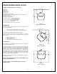
COMBUSTION AIR SUPPLY For a mobile home installation the stove must be connected to an outside source of combustion air. A 3” inside diameter metallic pipe, either flexible or rigid, may be attached to the inlet at the stove’s rear (refer to figures 4, 5 & 6). A rodent guard (minimum 1/4” wire mesh) must be used at the terminus (refer to figure 5). All connections must be secured and airtight by either using the appropriately sized hose clamp and/or UL-181-AP foil tape.
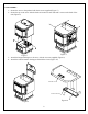
STOVE ASSEMBLY 1- Secure the stove to the pedestal with the 4 screws supplied.(Figure 7) 2- Secure the top to the stove with the brackets located on each side and 2 screws at the back of the unit.(Figure 8) Figure 8 Figure 7 3- Attach the hopper lid hinges to the stove with the 4 screws supplied (Figure 9) 4- Attach the control board to the hopper lid with the 4 nuts.
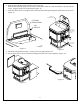
5- Plug the lead with the white connector to the lid switch. Run the other lead flat along the rear of the control panel, under the 2 tabs and attach to the tabs with Tywraps. Plug this lead to the control panel.(Figure 11) 6- Insert the rubber lid cover bumpers in the holes and attach side panel magnets and retainers as shown in Figure 12.
EQUIVALENT VENT LENGHT (EVL) The longer the run of pipe in your installation, the more restriction there is in the system. Therefore, larger diameter pipe should be used for longer runs. • Use 4” pipe if you have more than 15 feet of Equivalent Vent Length (EVL). • Horizontal runs shall not exceed 10 feet of EVL.
VERTICALLY WITH NEW CHIMNEY SYSTEM (Refer to Figure 18 & 19 for basement installation) 12" MINIMUM CLEARANCE TO ROOF NOTE: Follow L-Vent chimney manufacturer’s instructions. VERTICAL ROOF VENT OPTION: To achieve a centered vertical installation, a 45º elbow and a clean-out tee can be used to offset the pipe from the exhaust outlet to the rear center of the stove. STORM COLLAR ATTIC INSULATION SHIELD OPTION: Install L-Vent elbow in place of clean-out tee. Locate stove.
VERTICALLY INTO EXISTING MASONRY FIREPLACE VERTICAL ROOF VENT 18" NOTE: Follow L-Vent chimney manufacturer’s instructions. 1. 3" Have the masonry chimney inspected by a qualified chimney sweep or installer to determine its structural integrity. 2. You must run a pipe from the stove outlet to 18 inches above the top of the chimney. 3. Install a blanking plate and the chimney pipe, and if used the outside air pipe, as shown in Figure 20. 4.
INSERT INSTALLATION INSERT INTO EXISTING MASONRY FIREPLACE NOTE: Follow pipe manufacturer’s instructions. 1. 2. 3. 4. 5. Have the masonry chimney inspected by a qualified chimney sweep or installer to determine its structural integrity. You will need a pipe length equal to the chimney height from the hearth.
FACEPLATE ASSEMBLY 123456789- Install the damper rod as shown in Figure 25 & 26 Pull out the lead wires(Figure 27).Secure the top assembly with the 4 screws and insert the lid switch in the bracket at the rear of the right slide(Figure 28). Plug the white connector to the lid switch. Run the wire with the black connector towards the front and secure it using the wire straps and fixation hole(Figure 27) Assemble the sides to the top of the faceplate.(Figure 29) Attach the faceplate extension to the stove.
FACEPLATE EXTENSION Figure 29 Faceplate Assembly Figure 30 Faceplate extension assembly FACEPLATE EXTENSION CONTROL BOARD Figure 31 Control board installation Figure 32 Faceplate installation 15
TRIM ASSEMBLY U CLIP FASTENER Figure 34 Louvers installation Figure 33 Trim assembly & installation Figure 35 Decorative side panels installation 16
CLEARANCES COMBUSTIBLE SHELF 10 1/2" 11" 6" 7" ( FR FLOOR PROTECTION OM DO OR OP EN I 6" NG ) Figure 36 Clearances DOOR OVERLAY INSTALLATION In order to complete the assembly of your OSBURN HYBRID-35, you need to install the door overlay. 1- Position the overlay on the door frame and fix it in place from behind using the 4 screws. Note: It is not necessary to remove the glass or any other component to install the overlay.
OPERATION PROPER FUEL THIS STOVE IS APPROVED FOR BURNING PELLETIZED WOOD FUEL ONLY! Factory-approved pellets are those 1/4” or 5/16” in diameter and approximately 1” long. Longer or thicker pellets sometimes bridge the auger flights, which prevents proper pellet feed. Burning wood in forms other than pellets is not permitted. It will violate the building codes for which the stove has been approved and will void all warranties.
UNIT CONTROLS The blowers and automatic fuel supply are controlled from the panel on the HYBRID-35. The control panel functions are as follows: Note: 1- To display the available functions, just touch the control board at any place 2- Select the desired function *The display will turn itself off after 2 minutes. MODE BUTTON • When the on-off button is pressed, the stove will automatically ignite. The heat level must be selected manually to adjust the stove’s heat output to the desired level.
COMBEXtm Your stove uses a unique patented technology called COMBEX. As opposed to most other pellet stoves, which use only an exhaust blower, your HYBRID-35 uses a motor on which are mounted two housings with impeller blades. One housing serves for combustion, and the other for exhaust. This is why we refer to the combustion/exhaust blower throughout this manual.
SHUTDOWN PROCEDURE Turning your OSBURN stove off is a matter of pressing on the control panel. The blowers will continue to operate until internal firebox temperatures have fallen to a preset level. The stove cannot restart before it has completely shut down. SAFETY FEATURES a. Your stove is equipped with a manual reset high temperature switch (also called heat sensor or heat switch). The switch has a reset button on its backside.
OPERATING THE STOVE USING A THERMOSTAT A thermostat will help you maintain a constant house temperature automatically. A millivolt or 24 Volt thermostat is required. A fixed wall mount or remote model can be used. THERMOSTAT INSTALLATION • • • Unplug the stove from the power outlet. Connect two thermostat wires to the terminal block located on the lower right side of the back of the stove. To do so, loosen the two screws and insert the wires in the terminals. Tighten the two screws.
OPERATING SAFETY PRECAUTIONS PLEASE READ THIS! a. If you notice a smoldering fire (burnpot full but no visible flame) AND a heavy smoke buildup in firebox, immediately TURN OFF the stove, but DO NOT unplug it. Do not open the door, change the damper setting or tamper with any controls on the stove. Wait until smoke inside the firebox clears and blowers shut down. Do as instructed in “PRE-START-UP CHECK” and “LIGHTHING PROCEDURE”, then attempt to restart the fire.
MAINTENANCE FAILURE TO CLEAN AND MAINTAIN THIS UNIT AS INDICATED CAN RESULT IN POOR PERFORMANCE AND SAFETY HAZARDS. NEVER CLEAN WHEN HOT. NOTE: Inspect burn pot periodically to see that holes have not become plugged. If so, clean thoroughly. BAFFLE ASH REMOVAL The HYBRID-35 stove has an ash drawer located under the firebox (not available for insert installation*). To remove ashes: a. Make sure fire is out and the firebox is cool. b. Open the door and remove the baffle from the firebox.
VACCUM USE If a vacuum is used to clean your stove, we suggest using a vacuum designed for ashes. Some regular vacuums and shop vacs leak ash into the room. Your vacuum or shop vac may have a special filter or bag available to eliminate this leakage. CLEANING a. b. c. d. Heat Exchange Tubes – Your HYBRID-35 stove is designed with a built-in heat exchanger tube cleaner. This should be used weekly to remove accumulated ash on the tubes.
BLOWERS AND PRESSURE SWITCH PROBE PROBE CONNECTOR DANGER: RISK OF ELECTRIC SHOCK. DISCONNECT POWER BEFORE SERVICING UNIT. • • Blower Cleaning – Over a period of time, ashes or dust may collect on the blades of both the combustion/exhaust blower and convection blower. Periodically, the blowers should be cleaned as the ash and dust can impede performance. The combustion/exhaust blower can be accessed by opening the left, right, and back panels.
TROUBLESHOOTING When your stove acts abnormally, the first reaction is to get help. This guide may save you time and money by enabling you to resolve simple problems yourself. Problems can be caused by: 1) poor fuel; 2) poor operation or maintenance; 3) poor installation; 4) component failure; 5) factory defect. You can usually solve problems related to 1 and 2. Your dealer can solve problems related to 3, 4 and 5.
STOVE SHUTS OFF AND SHOWS ERROR CODE “E” Possible Causes: Possible Remedies: (Unplug stove first when possible) 1. The hopper is empty. Refill the hopper. 2. The burn pot holes are blocked. Remove the burn pot and clean it thoroughly. 3. The air damper is too far open for a low feed setting. If burning on the low setting, you may need to close the damper all the way slide the air supply toward the minimum setting. 4. The air inlet, the interior chambers, or exhaust system has a partial blockage.
STOVE FEEDS PELLETS, BUT WILL NOT IGNITE AND SHOWS ERROR CODE “L” Possible Causes: Possible Remedies: 1. Air damper open too far for ignition. Adjust the air supply toward the minimum setting for startup. In some situations, it may be necessary to have the damper completely closed for ignition to take place. After there is a flame, the damper can then be adjusted for the desired feed setting. 2. Blockage in igniter tube or inlet for igniter tube. Remove the burn pot and clean it thoroughly.
STOVE STOPS FEEDING PELLETS AND SHOWS ERROR CODE “H” Possible Causes: Possible Remedies: 1. The L-250 automatic high temperature switch is located on the auger housing top and bottom It will send a signal to the control board if the auger housing overheats. Wait until the stove cools down. YOU NEED TO INSPECT YOUR UNIT AT THIS POINT. There might be a problem with another component or the installation, causing the stove to overheat. Reset the stove and restart it.
GLASS SOOTS UP VERY FAST FLAME IS LAZY, DARK, AND HAS BLACK TIPS AFTER STOVE HAS BEEN ON FOR A WHILE, THE BURNPOT OVERFILLS Possible Causes: Possible Remedies: 1. Stove or vent pipe is clogged, which restricts airflow through the burn pot. Follow all cleaning procedure in the maintenance section of the owner’s manual. 2. Vent pipe installed improperly. Check to make sure the vent pipe has been installed according to the instructions in the owner’s manual. 3.
ELECTRICAL DIAGRAM THERMOSTAT TERMINALS N.O. HOPPER LID SWITCH N.O. ELECTRONIC BOARD CONTROL BOARD THERMISTOR L2(LINE COMMON) L1(LINE HOT) L1(LINE NO CONNECTED) FRAME GROUND L-250 RESET N.C. AIR FLOW PRESSURE SWITCH N.O. L-250 N.C. COMBUSTION/EXHAUST BLOWER AUGER MOTOR IGNITER L-250 N.C. F-160 N.O.
REPLACEMENT PARTS Contact an Authorized OSBURN Dealer to obtain any of these parts. Never use substitute materials. Use of non-approved parts can result in poor performance and safety hazards. ITEM Airflow Pressure Switch Air Switch Hose Auger Motor Burn Pot Burn pot gasket(2 requires) Control Board(Touch screen) PC Board Combustion/Exhaust Blower Assembly Convection Blower Door Gasket Hot Rod Igniter Thermistor F-160 Convection blower heat sensor L-250 Automatic High Temp.
OSBURN LIMITED LIFETIME WARRANTY The warranty of the manufacturer extends only to the original consumer purchaser and is not transferable. This warranty covers brand new products only, which have not been altered, modified nor repaired since shipment from factory. Proof of purchase (dated bill of sale), model name and serial number must be supplied when making any warranty claim to your OSBURN dealer. This warranty applies to normal residential use only.