
Indoor Fireplace User Manual


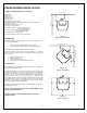


FREESTANDING INSTALLATION
6
SIDE WALL
6"
BACK WALL
2" *
3"
Figure 1
Back wall installation
2"
3"
3"
2"
ADJACENT WALL
ADJACENT WALL
Figure 2
Corner installation
HYBRID-35 FREESTANDING PELLET STOVE
Width: 22 1/2”
Height: 29”
Depth: 24 1/2”
Weight: 195 lbs.
Flue size: 3” or 4”
Hopper Capacity: Up to 35 lbs.
(This can vary slightly depending on pellet size, length, and diameter)
EPA status: exempt
Burn rate: 1 lb. to 4.0 lbs. per hour
BTU range: 8,200 to 35000
Electrical consumption: 3.5 Amps lighting cycle
2.5 Amps. continuous duty
Control board fuses: Main: 7.5A-250V fastblow
Igniter: 5A-250V fastblow
Electrical requirement: 120VAC 15A
Approved installations: mobile home, conventional
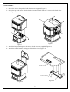
PREPARATION
Factory packaging must be removed, and some minor assembly work is
required prior to installation:
• The door overlay must be installed on the door frame;
• The louver kit must be installed in front of the heat exchanger.
NOTE: Normally, your dealer will perform these functions.
To remove ashes, use the ash pan or a vacuum cleaner. If you want to
use the ash pan, you will have to remove the plate located at the right side
of the burn pot.
1- Remove the three screws
2- Remove the plate
3- Put the three screws back
4- Use the ash dump cap provided with the stove
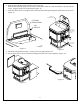
CLEARANCES
The HYBRID-35 has been tested and listed for installation in regular and
mobile homes.(refer figure 1 & 2)
FLOOR PROTECTION: minimum 6” in the front and 6” on each side. The
stove must be placed on a continuous (grouted joints) non-combustible
material such as ceramic tile, cement board, brick, 3/8” millboard or
equivalent, or other approved or listed material suited for floor protection.
NOTE: ceramic tile, or any tile, must be laid on a continuous non
combustible sheet to prevent the possibility of embers falling through to the
combustible floor if cracks or separation should occur in the finished
surface, this also applies to floor protection for Built-in raised hearths.
Check local codes for approved alternatives.
Clearances are measured from the sides, back and face (door opening) or
stove body (refer to fig. 3).
DO NOT USE MAKESHIFT MATERIALS OR COMPROMISES IN THE
INSTALLATION OF THIS UNIT.
INSTALL VENT WITH CLEARANCES SPECIFIED BY THE VENT
MANUFACTURER.
6"
6"
6"
Figure 3
Floor protection