www.osram.com/ledset Application guide. The LEDset interface.
CONTENTS General notes: As the specifications of the applied components are subject to change, OSRAM does not take liability for the technical accuracy of the application solutions shown in this application guide. For current specifications, please refer to the data sheets of the respective components. Please also note that LED standards are changing rapidly and that this application guide can therefore only reflect the status of the listed standards on the date published.
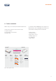
CONTENTS 1. Introduction 1.1. Features and benefits 4 5 2. LEDset specifications 2.1. General overview 2.2. LEDset characteristic 2.2.1. General description 2.2.2. Implementation in the OSRAM ECG 2.3. Technical details 2.3.1. Bias current (Iset) 2.3.2. +12Vset 2.3.3. Fault protection 2.3.4. Insulation 2.3.5. Color coding 2.3.6. Cable length 2.3.7. Fault conditions/troubleshooting 2.3.7.1. Incorrect wiring 2.3.7.2. Missing control wire (Vset) 2.3.8.
INTRODUCTION 1. Introduction LED technology is changing the world of general lighting. In luminaire design, however, the various benefits of LEDs, e.g. their high level of flexibility in operating luminaires, can only be achieved with perfectly matched control gears. This is further complicated by the rapid improvement of the efficacy and current capability of LED technologies, which asks for even greater adaptability of the corresponding control gears.
INTRODUCTION 1.1.
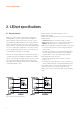
LEDset SPECIFICATIONS 2. LEDset specifications 2.1. General overview LEDset is a 3-wire analog control interface designed for OPTOTRONIC® constant-current LED power supplies. It allows setting the output current of the electronic control gear (ECG) by providing a highly accurate voltage reference (Vset) to the ECG. Thanks to the control accuracy and simplicity of LEDset, control gears become highly adaptable and can cover a wide range of applications.
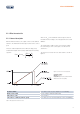
LEDset SPECIFICATIONS 2.2. LEDset characteristic 2.2.1. General description With the LEDset interface, the output current can be defined relative to the maximum nominal output current of the control gear. The basic relationship between the LEDset voltage (Vset) and the ECG output current (Iout) is defined by the following equation: Iout Inommax (Vset 1) where Inommax is the maximum nominal output current of the ECG and Vset voltage is the voltage between Vset and GNDset.
LEDset SPECIFICATIONS Note: Vmin is the Vset voltage value corresponding to the minimum deliverable current (Imin) of the ECG. The Imin is specified in the datasheet of the applied ECG. Based on the LEDset relationship between Iout and Vset, it is possible to calculate the typical Vmin of the ECG. 2.2.2.
LEDset SPECIFICATIONS 2.3. Technical details This chapter gives a general overview of the technical details of the LEDset interface. For further details and deviations from this basic information, please refer to the datasheet and instruction sheet of the respective control gear. 2.3.1. Bias current (Iset) 2.3.4.
LEDset SPECIFICATIONS 2.3.5. Color coding 2.3.6. Cable length The color coding for the connector of the LEDset interface is defined as follows: The maximum length of LEDset cables should not exceed 2 m. Further limitations to cable length generally derive from EMI emission or immunity issues or directly from product specification details. For detailed information, please refer to the datasheet or instruction sheet of the respective LEDset control gear.
LEDset SPECIFICATIONS 2.3.8. Connection of multiple ECGs Depending on the LEDset control gear, the Vset signals can be connected in parallel to set the current of multiple ECGs by a resistor. This connection is allowed in case of a local dimming application on a luminaire supplied by more than one ECG.
LEDset APPLICATIONS 3. LEDset applications 3.1. Current setting 3.1.1. Setting by external resistor If the application requires a specific fixed output current, the easiest way to set the output current is to apply a resistor between Vset and GNDset. As mentioned in chapter 2.3.1., the LEDset interface is an active interface that is able to generate a constant current output (Iset) and thus allows the use of “passive” circuits (e.g. resistor) to achieve the setting voltage (Vset).
LEDset APPLICATIONS The following table shows the output current values obtained by applying a 1 % resistor (from E96 series unless otherwise specified) for two different ECGs with a nominal current of 700 mA and 1500 mA, respectively. Rset – E96 series (unless otherwise specified) Vset [V] Iout/Inom [%] Inom [mA] = 700 Inom [mA] = 1500 0 0.0 0 0 0 3830 1.0 1 4 8 7500 2.1 12 82 176 11300 3.1 23 163 349 14700 4.0 34 235 505 15000 4.1 35 242 518 19100 5.
LEDset APPLICATIONS Note 1: The E96 series covers a wide range of values. The table contains only some sample values of this series. Please check the standard E96 series to find the value best suited for meeting your current setting requirements. Note 4: Since the Iset current value is very low, the power rating of the resistor is not an issue to be considered when selecting the resistor (considering a maximum value of 50 kΩ PRset = 3.8 mW).
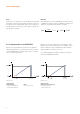
LEDset APPLICATIONS 3.1.2. Step dimming (StepDIM) Based on the previous chapter (3.1.1.), the current setting by resistor can be easily extended by an additional step dimming function. By switching between two external resistance values, the output current can be changed to two different levels (i.e. one to set the nominal current to 100 % and one to step down to 40 %). Shorting the Vset to GNDset allows turning off the LED module while the ECG is still supplied with mains voltage.
LEDset APPLICATIONS Switching can be carried out either by a switch (manual activation, see figure 7a) or by using a relay (see figure 7b). While Rset1 sets the current level Iout1, the equivalent parallel resistance RsetEQ (Rset1||Rset2) sets Iout2. Note: In both cases (7a and 7b), two main issues need to be considered when selecting the components: • Performance The relay contacts or switch contacts must be suitable for applications with a very low current.
LEDset APPLICATIONS 3.2. Local dimming 3.2.1. Potentiometer application If an application requires the dimmability of a luminaire, a simple and economical solution can be to implement a local dimming function by a logarithmic or linear potentiometer. In this case, the term “local dimming” refers to the possibility to set the current of a single luminaire system by a potentiometer. Figure 8: Local dimming – potentiometer application.
LEDset APPLICATIONS 3.2.2. Light sensor application Daylight compensation can be easily obtained with the LEDset interface by connecting existing commercial light sensors (only plug-and-play sensors as described in the following chapter). Light sensing can be approached by using standard 1…10 V-compatible light sensors or by developing light sensors from IC chips and converting their output signal to the Vset range of the LEDset interface. 3.2.2.1.
LEDset APPLICATIONS 3.2.2.2. Using customized sensors Various light sensors can be used in place of the previously mentioned OSRAM DIM MICO/PICO. Once the output sensor is compatible with the LEDset interface, the resulting control possibilities can perfectly fit the needs of the application.
LEDset APPLICATIONS 3.2.2.3. General notes on local dimming: LEDset, “current set” combination For some applications, the turn-off capability provided by the LEDset characteristic above 11 V might not be an appropriate feature. Therefore, some LEDset ECGs can combine the LEDset interface with the so-called “current set” (CS) feature. Product examples are the OT 35/220-240/700 LTCS and OT 45/220-240/700 LTCS (LTCS means “LEDset” (LT) and “current set” (CS)).
LEDset APPLICATIONS Figure 11: Local dimming – example of the LTCS characteristic of the OT 35(45)/220-240/700 LTCS. Above 10 V and higher, the output current is maintained at its maximum nominal value without turning off the ECG. In this case, the accuracy features of the LEDset interface can also be combined with inflexible light sensors with an output range higher than 11 V. This capability to maintain the Inommax from 10 to +12 V +10 % without turning off the ECG output easily solves possible issues.
LEDset APPLICATIONS 3.3. Thermal derating With its simple and flexible properties, the LEDset interface allows users to manage the LED module temperature directly with the ECG. Luminaire manufacturers prefer to customize their products via different approaches to manage temperature deratings and/or protections. One-step (switch-off) or two-step (intermediate current level and switch-off) solutions satisfy the simpler, more common requirements for thermal protection/management (figures 12a and 12b).
LEDset APPLICATIONS Application solutions Complexity level For detailed information, please see chapters: a) Low 3.3.1. Overtemperature protection 3.3.1.1. Application solution 1 – TMP300 solution 3.3.1.2. Application solution 2 – LM26 solution 3.3.1.3. Application solution 3 – NPC SM6611 solution 3.3.1.4. Application solution 4 – SI S-5841 solution 3.3.1.5. Application solution 5 – MM3488 solution Medium 3.3.2. Overtemperature protection (discrete NTC) 3.3.2.1.
LEDset APPLICATIONS 3.3.1. Overtemperature protection A possible approach for overtemperature protection is to simply use the so-called “temperature switch ICs” – an easy, relatively cheap and low-component-number solution. 3.3.1.1. Application solution 1 – TMP300 solution TMP300 (Texas Instruments) is a digital output temperature switch IC. Its voltage supply range is 1.8–18 V, therefore it can be directly supplied by the LEDset +12Vset terminal.
LEDset APPLICATIONS The schematic of the circuit is shown in figure 13. Proper by-pass capacitors (100 nF 25V X7R SMD type) should be added on the supply line and Rtemp to ensure a noiseless application. The hysteresis of the temperature threshold can be set in two different ways: • 5 °C if pin 4 is grounded; • 10 °C if pin 4 is connected to pin 6 (Vcc). A setting resistance (Rset) can be integrated into the circuit in order to set the operating current of the system as described in 3.1.1.
LEDset APPLICATIONS 3.3.1.2. Application solution 2 – LM26 solution LM26 (National Semiconductor) is a digital output temperature switch IC with a factory-programmed trip point ranging from -55 °C to 110 °C (in increments of 1 °C). LM26 can have four different configurations of the digital output. Version C (active-high, push-pull on OS output) is needed for this application. Figure 16: Thermal protection – LM26 solution. In figure 16, a reference schematic is shown.
LEDset APPLICATIONS 3.3.1.3. Application solution 3 – NPC SM6611 solution SM6611 (NCP) is a temperature switch IC able to change the state of an output pin (invert) when the chip temperature exceeds a preset temperature (TsetTH). The TsetTH temperature detection is managed by hysteresis (10 °C) to prevent unstable output switching (sensed temperature close to the preset temperature). SM6611 series propose 6 preset TsetTH temperatures, 2 output configurations (push-pull, open drain).
LEDset APPLICATIONS 3.3.1.4. Application solution 4 – SI S-5841 solution The SI S-5841 (SI – Seiko Instruments Inc.) series is a temperature switch IC which detects a certain temperature and sends a signal to an external device. Various combinations of the parameters such as the detection temperature, output form and output logic can be selected. In package SOT-23-5, five TsetTH temperatures are available as factory settings (+55 °C, +65 °C, +75 °C, +85 °C, +95 °C).
LEDset APPLICATIONS 3.3.1.5. Application solution 5 – MM3488 solution The MM3488 (MITSuMI) is a temperature switch IC that changes the IC output level from “low” to “high” when the temperature around the IC reaches the detection temperature. With the hysteresis function (5 °C, 10 °C, 15 °C), the IC output level returns to “low” when the ambient temperature drops to the temperature hysteresis selected after detection. Detection temperature TsetTH can be selected in steps of 1.
LEDset APPLICATIONS The TC620 and TC621 (from Microchip) are programmable logic output temperature detectors designed for use in thermal management applications. The TC620 features an onboard temperature sensor, while the TC621 connects to an external NTC thermistor for remote sensing applications. the user-programmed limits. The CONTROL (hysteresis) output is driven high when the temperature equals the “high limit” setting and returns to “low” when the temperature falls below the “low limit” setting.
LEDset APPLICATIONS Figure 23: TC620 solution – output characteristic. Figure 24: TC620 solution – RTRIP vs. temperature. Example: Conditions: TsetH = 80 °C TsetL = 70 °C In order to achieve the 70 % of Inommax, the equivalent parallel resistance RsetEQ (Rset1||Rset2) to be chosen must be about 26.7 kΩ (see table 4 in chapter 3.1.1.). IoutH = 0 % Inommax IoutL = 70 % Inommax With the TC620 datasheet, it is possible to calculate the resistance value for the temperature trip points: RTRIP 0.5997 T 2.
LEDset APPLICATIONS Note: For a precise calculation, the VCEsat of Q2 should also be considered. For a BC847 transistor, the voltage drop is in the range between 40 and 50 mV depending on the temperature of the device. In figure 25, the voltage drop relates to a temperature range between -55 and +150 °C. In the described application solution, however, the temperature of Q2 is generally within a tighter range when it is active. Therefore, the voltage drop variation will be smaller than in figure 25.
LEDset APPLICATIONS 3.3.1.7. General notes on IC temperature switches: choice and usage • For all the above application solutions, the Rset can be either a fixed resistor or a variable resistor usable for local dimming (as described in 3.2.). • For all the above application solutions except application solution 6, the output of the IC (direct output or output via transistor) can be connected to the Vset line via an Rset2 resistor.
LEDset APPLICATIONS 3.3.2. Overtemperature protection (discrete NTC) The application solutions analyzed in 3.3.1. show the implementation of the LED module’s overtemperature protection by means of a dedicated IC chip that integrates the temperature sensing. Similar results can be achieved by implementing electronic circuits based on a discrete NTC component and an OPAMP (operation amplifier) which acts like a comparator. Benefits of this solution: • The cost of the circuit components is lower.
LEDset APPLICATIONS The circuit configuration allows setting a hysteresis between on and off state, thus avoiding spurious and unwanted light flickering/toggling: focusing on the comparator circuit, the R1, R4 and R3 resistors set the trip threshold voltages VTRIP+ (related to TsetTH- ΔTHyst) and VTRIP- (related to TsetTH). These VTRIP voltages are compared with the voltage related to the divider realized by the R2 and NTC resistors. Based on the NTC characteristic (resistance vs.
LEDset APPLICATIONS 3.3.2.2. Application solution 2 – overtemperature management by comparator: two-step output The following application is basically similar to the one described in chapter 3.3.1.6. Application solution 6 – TC620(1) solution. The circuit is obtained by using a low-cost dual OPAMP, which allows setting two trip temperatures (TsetH and TsetL) and their relative hysteresis by extending the circuit functionality described in chapter 3.3.2.1.
LEDset APPLICATIONS Example: Requirements: TsetH = 70 °C TsetL = 55 °C ΔTHyst = 5 °C Iout = Inommax Ioutwarning = 60 % Inommax Ioutfault= 0 mA By selecting the following components, the result shown in figure 33 can be achieved: R1 = 68.1 kΩ 0603 1 % (general purpose) R2 = 270 kΩ 0603 1 % (general purpose) R3 = 560 kΩ 0603 1 % (general purpose) R4 = 20.
LEDset APPLICATIONS 3.3.2.3. Application solution 3 – overtemperature management: continuous derating and switch-off The following application shows a cost-efficient solution obtained by using a lowcost dual OPAMP (such as LM2904). The idea is to manage the overtemperature state of the LED module by continuously derating the current in a defined temperature range (from TsetL to TsetH), ending with the switch-off of the supply output current when the protection temperature is reached (TsetH).
LEDset APPLICATIONS Example: Requirements: TsetH = 75 °C TsetL = 60 °C ΔTHyst = 5 °C Iout = Inommax Ioutwarning = from 100 % to 60 % Inommax in a linear way Ioutfault= 0 mA By selecting the following components, the result shown in figure 37 can be achieved: R1 = 100 kΩ 0603 1 % (general purpose) R2 = 270 kΩ 0603 1 % (general purpose) R3 = 0R 0603 1 % (general purpose) R4 = 681 kΩ 0603 1 % (general purpose) R5 = 36.
LEDset APPLICATIONS 3.3.2.4. Application solution 4 – LEDset and current set combination: direct NTC connection As described in chapter 3.2.2.3. General notes on local dimming: LEDset, “current set” combination, there are ECGs which can combine the LEDset interface characteristic with the optional current set configuration. ECGs with this kind of combination offer another very simple and economical application: the direct connection of an NTC.
LEDset APPLICATIONS For this kind of application, the choice of the NTC is fundamental to meet the requirements in terms of the TsetTH (temperature from which to start the derating) and the slope rate (based on the NTC parameters B25/85 and B25/100) of the characteristic Iout vs. Tset above the TsetTH. For the fine tuning, the Rp resistor allows changing the TsetTH point to reach the temperature required to start the derating.
LEDset APPLICATIONS 3.3.2.5. Application solution 5 – overtemperature management: microcontroller (MCU) approach Since the cost of small 8-bit microcontrollers has dropped over the past years, they have become an affordable solution for implementing simple functionalities and increasing the flexibility of a system at the same time. These microcontrollers are equipped with various kinds of peripherals, e.g.
LEDset APPLICATIONS Note: The DAC interface can be implemented in various ways. The only thing to take into account is that the DAC circuit must be able to sink the Iset current (274 µA) imposed by the Vset connection. Figure 42: Thermal derating – MCU solution. A simple voltage regulator is required to regulate the +12Vset to 5 V which are needed to supply the MCU. The voltage divider R2/NTC is connected to the same 5 V supply as the MCU.
LEDset APPLICATIONS Using two lookup tables – one for the temperature and one for the Vset – allows the designer to be very flexible: • The NTC can be changed by modifying only the points of the temperature lookup table. • The Vset output characteristic can be changed (e.g. when the temperature monitor system is used for a different luminaire) by modifying only the points of the Vset lookup table.
LEDset APPLICATIONS Figure 44: Thermal derating – MCU solution: module status signaling by an LED. Figure 45: MCU solution: module status signaling/communication by IR interface. The MCU approach can be a bit more expensive and may require more design development skills (need of HW and SW development) compared to the application solutions discussed earlier in this chapter.
LEDset APPLICATIONS 3.4. +12Vset auxiliary supply 3.4.1. Aesthetic use The LEDset interface provides a +12Vset supply voltage that can be used in different ways: not only for thermal management, daylight compensation and aging compensation, but also for aesthetic purposes. In addition to supplying the circuits shown above, the +12Vset supply voltage can also be used for some “lowpower” LED applications, e.g. ring backlighting of a luminaire switch (see figure 48).
LEDset APPLICATIONS 3.4.2. Active cooling Future generations of the LEDset interface might have a higher power capability via the +12Vset auxiliary supply. It will then be possible to drive an active cooling system such as a fan (e.g. when high-power LED modules require forced cooling). The following block diagram shows such an application. Figure 49: +12Vset auxiliary supply – active cooling system.
LEDset APPLICATIONS 3.5. Constant lumen output The application example in chapter 3.3.2.5. Application solution 4 – overtemperature management: microcontroller approach shows that – in addition to the thermal management of the module – more features can be added thanks to the presence of the MCU: • By using a general-purpose timer of the MCU, it is possible to measure the working time of the module and store it to memory.
LEDset APPLICATIONS 3.6. Combination of features With LEDset, some LED control features can be combined with one single interface. Figure 51 gives an overview of possible combinations. OSRAM will assist you in creating your own specific solution. Features that can be combined: • Temperature control • Daylight sensing • Local dimming by potentiometer (connected to the control module) • Use of external switch for on/off switching (e.g.
www.osram.com/ledset Global presence. OSRAM supplies customers in 148 countries. • 85 companies and sales offices for 122 countries • 26 countries served by local agents or OSRAM GmbH, Munich OSRAM associated companies and support centers: OSRAM AG Head Office Hellabrunner Strasse 1 81543 Munich Phone +49 (0) 89-6213-0 Fax +49 (0) 89-6213-20 20 www.osram.