www.osram.de www.osram.
CONTENTS Contents Electronic control gear for metal halide lamps and highpressure sodium vapor lamps have increased substantially in importance in the last few years and now represent the current state of technology. This technical guide highlights the properties of the electronic control gear and their differences from the conventional magnetic control gear when in operation. It also provides hints and tips for the correct installation and operation of the devices according to the applicable standards.
CONTENTS Contents 1. The system HID lamp and ECG 5 1.1. High-pressure discharge lamps 5 2.2.4.1. Wire and cabling types 13 1.2. The POWERTRONIC® ECG 5 2.2.4.2. Cabling cross-section 13 1.2.1. Product range 6 2.2.4.3. Cable length between ECG and lamp 13 1.2.2. Operating principle 6 2.2.4.4. Cable layout 14 1.2.3. Benefits of the intelligent POWERTRONIC® ECG 6 2.2.4.5. Wiring plans for integration of POWERTRONIC® ECG PTi and PT-FIT 14 1.2.4.
CONTENTS Contents 2.4. Hints on luminaire design 28 2.4.1. Thermal coupling 28 2.4.2. Ventilation slits, cooling fins 28 2.4.3. Materials that can be used in luminaire structures 28 2.4.4. Installation-friendly ECG 28 2.4.5. Installation space for independent devices 30 2.4.6. Plug-&-Play installation with cable/socket system 30 4. ECG label 39 5. The System+ guarantee 40 6. Further information 40 7. Glossary of key words 41 2.4.7.
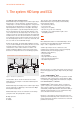
THE SYSTEM HID LAMP AND ECG 1. The system HID lamp and ECG 1.1. High-pressure discharge lamps Metal halide lamps and high-pressure sodium vapor lamps both belong to a group referred to as high-pressure discharge lamps. In contrast to what happens in low-pressure discharge, the discharge tube in such lamps operates at high temperatures and pressures. The light in discharge lamps is generated in a gas discharge that takes place in the arc tube between two electrodes after ignition.
THE SYSTEM HID LAMP AND ECG 1.2.1. Product range POWERTRONIC® ECGs are available in a variety of wattages. For indoor applications, the PTi and PT-FIT control gear (POWERTRONIC® indoor) have been developed for operation of HCI and HQI lamps. For this area of application there are ECGs available that are capable of being connected to one or two lamps. PTo control gear (POWERTRONIC® outdoor) have been developed for outdoor operation of HCI, HQI and NAV lamps. 1.2.2.
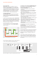
THE SYSTEM HID LAMP AND ECG Comparison of CCG and POWERTRONIC® Energy consumption Magnetic control gear (CCG) POWERTRONIC® electronic control gear 100 For indoor applications: 10 to 15 % savings over the whole service life For outdoor applications: up to 30 % savings over the whole service life through dimming function (3DIM) Up to 30 % depending on lamp type and application Lamp life 100 Lamp warm-up Depends on lamp type: generally approx.
THE SYSTEM HID LAMP AND ECG 1.2.5.2. Installation of devices in luminaires or mounting the types with cable clamp in suspended ceilings POWERTRONIC® ECGs are available in two different versions – each tailor-made for the requirements of the lighting application they are being used in.
THE PRODUCT IN OPERATION 2. The product in operation 2.1. Supply voltage 2.1.1. Permissible voltage range All POWERTRONIC® ECGs for the operation of high-pressure discharge lamps are designed for sinusoidal alternating voltages at 50 to 60 Hz in a nominal voltage range of 220–240 V. Deviations of -10 %/+6 % from each of the nominal voltage boundary values are permissible – even within such a range, thanks to the ECG, lamps will still remain within the optimal working range set for the relevant lamp type.
THE PRODUCT IN OPERATION 2.1.3. Undervoltage > 198 V The operation of ECGs below the permissible nominal voltage range ("undervoltage") is not permitted and may lead to the following effects: • Lamp operation outside nominal values → Effect on lamp life • Uncertain lamp ignition, as ignition is guaranteed only above 198 V.
THE PRODUCT IN OPERATION 2.1.7. Overvoltage protection In conventional three-phase installations, electronic control gears are generally suited to an input voltage of between 220 and 240 V. Depending on the load balance, this value may rise in case of the missing or unsatisfactory contact of the neutral conductor to a maximum value of √3 x 230 V = 400 V: POWERTRONIC® ECGs are not suitable for operation where loading is unbalanced.
THE PRODUCT IN OPERATION 2.2.2.3. Insulation resistance in lighting installations The insulation resistance in lighting installation (> 1.0 MΩ) must be measured in accordance with IEC 60364-6 Section 61.3.
THE PRODUCT IN OPERATION 2.2.4. Wiring 2.2.4.1. Wire and cabling types When wiring luminaires in order to use high-pressure discharge lamps, it is important to consider the U-OUT voltage on the ECG's label. The U-OUT value gives information on the types of wiring to be used. 2.2.4.3.
THE PRODUCT IN OPERATION 2.2.4.4. Cable layout In order to achieve good radio interference suppression and the greatest possible degree of operational safety, attention should be paid to the following points for wiring: 1. Keep the cable between ECG and lamp as short as possible. 2. In order to prevent coupling of lamp lines with mains lines, avoid laying them parallel to each other. The distance between such cabling should be at least 5 cm.
THE PRODUCT IN OPERATION 2.2.4.6. Wiring plans for downlights with POWERTRONIC® ECG with cable clamp The wiring of independent devices has particular requirements, particularly from the point of view of the EMC. For this reason the following section is dedicated to dealing with such applications. Notes: • Use short lamp cabling: approx. 0.5 m • The PE-LUM connection may only be used for earthing the luminaire. Where longer cables (<1.
THE PRODUCT IN OPERATION 2.2.4.7. Wiring plans for POWERTRONIC® ECG PTo The PTo devices1 provide 3 different dimming modes; these are provided under the 3DIM feature.
THE PRODUCT IN OPERATION Easy ways of increasing the number of ECGs per circuit breaker: • Use of the EBN-OS inrush current limiter • The use of AC relays for each group with the maximum permissible number of ECGs. These relays should be connected so that they close as soon as mains voltage is applied. The retardation of the relays will cause the inrush current for the 2nd group to occur with a delay as compared to the 1st group.
THE PRODUCT IN OPERATION 2.3.5. Power factor, compensation For all devices that consume electricity, the power factor λ is the ratio of effective power (PEffect = U x IEffect) to apparent power (PAppar = U x I). This value is affected both by the phase displacement cos φ between the current and the voltage and by the current distortion ε (deviation from the sinusoidal shape). 2.3.6.
THE PRODUCT IN OPERATION 2.3.6.1. Device temperature tc According to EN 60598-1 tc (temperature casing) is the highest permissible temperature that may occur during normal operation under the nominal voltage (or at the maximum value of a rated voltage range) on a particular marked point of the ECG (the tc test point). It is thus a safety-relevant value.
THE PRODUCT IN OPERATION 2.3.6.4. Practical assessment of the service life and thermal properties of an ECG There are two ways of clarifying the life expectancy of an ECG. 1) Without any temperature measurement Comparing the ta values of the ECG with the ta temperature data shown on its technical datasheet can give an indication of the ECG life expectancy 2) With temperature measurement in a luminaire Set an ambient temperature for the luminaire (e.g.
THE PRODUCT IN OPERATION Extreme overheating can destroy components very quickly. Long-lasting high temperatures can also lead to premature failure. In some areas there may be an almost exponential relationship between the failure rate of an electronic component and the thermal load it is subjected to. Due to this exponential relationship, exceeding the permissible tc temperature can drastically reduce the service life of an ECG.
THE PRODUCT IN OPERATION 2.3.7. General hints on installation in relation to temperature It is essential to ensure that lamp and ECG do not heat up each other in the luminaire and that the ECG power loss can be safely dissipated even at the maximum expected ambient temperatures and/or supply voltage. The temperature at the tc test point of the ECG may not be exceeded even at the maximum expected ambient temperature and/or supply voltage.
THE PRODUCT IN OPERATION 2.3.8. ECG's ability to withstand frequent on/off switching The ability of electronic control gears to withstand on/off switching is always determined in the form of the number of possible lamp starts per day. By multiplying this number with the expected service life of the gear, the total number of switchings for professional electronic control gear can be calculated.
THE PRODUCT IN OPERATION 1) Shutdown mechanism – increase in the re-ignition peak In conventional operation the re-ignition peak is a peak in the lamp's operating voltage, after current and voltage pass through zero. With sinusoidal lamp current, the current decreases little by little, before reaching zero. As a result of the continuously decreasing current the lamp plasma cools down.
THE PRODUCT IN OPERATION The user can choose here between three different dimming modes: Where no control line exists in the system the user can use the AstroDIM function. Using it one can dim the luminaire without an external control by defining a time window (e.g. within six hours) within which the lamp is dimmed from 100 to 60 % and is then turned back up again. Lumen All three dimming settings can be adjusted using a software tool and can be changed back again at any time.
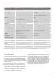
THE PRODUCT IN OPERATION Dimming means reducing wattage to save energy. The following values emerge per DIM level, lamp type and wattage for each system. Light and wattage details for a PTo 50 3DIM system PTo 50 3DIM HCI-TT 50W WDL NAV-T 50W Super DIM-Level [%] PL [W] PS [W] PHI [lm] ETA [lm/W] ETA sys [lm/W] CT [K] Ra PHI [lm] ETA [lm/W] ETA sys [lm/W] 100 50.5 56.4 4960 98.1 87.9 3041 79 4005 79.3 71.0 90 45.7 51.2 4375 95.7 85.5 3183 75 3380 73.9 66.0 80 40.6 45.
THE PRODUCT IN OPERATION Light and wattage details for a PTo 100 3DIM system PTo 100 3DIM HCI-TT 100W WDL NAV-T 100W Super DIM-Level [%] PL [W] PS [W] PHI [lm] ETA [lm/W] ETA sys [lm/W] CT [K] Ra PHI [lm] ETA [lm/W] ETA sys [lm/W] 100 98.0 106.1 10695 109.1 100.8 3009 86 10670 108.8 100.5 90 85.0 92.3 9215 108.4 99.9 3057 83 9420 110.8 102 80 74.2 80.9 7870 106.1 97.3 3151 79 8020 108 99.1 75 67.0 73.4 6930 103.5 94.3 3255 76 6550 97.7 89.2 70 62.
THE PRODUCT IN OPERATION 2.4. Hints on luminaire design The general recommendations on luminaire design by IEC and the national authorities (VDE, KEMA, ANSI, etc.) should be followed. In addition, it should be noted that POWERTRONIC® systems may be subject to ignition voltages of up to 4.5 kV. Components (sockets, cabling, etc.) and materials should be selected in accordance with these requirements.
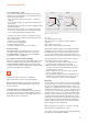
THE PRODUCT IN OPERATION B version for installation in luminaires: PTi I version for independent mounting with cable clamps: Figure 29: PT-FIT 70/220-240 B Figure 31: PTi 70/220-240 I • Mounting the device using grommets on the bottom • Plug terminals for fast connection and release of wires without the need for tools • The luminaire casing must provide protection in order to satisfy the EN 60598-1 and EN 61347-2-12 safety standards • Large terminal compartment gives good access to terminals • A gener
THE PRODUCT IN OPERATION 2.4.5. Installation space for independent devices POWERTRONIC® PTi/PT-FIT I devices with integrated cable clamp are ideal for use in suspended ceilings. In such applications the diameter of the ceiling cut-out depends on the installation height available.
THE PRODUCT IN OPERATION For all versions it is important to keep in mind the typical conditions required for discharge lamps; namely high ignition voltage and temperatures. The selection and technically correct integration of lamp sockets in accordance with the applicable standards (e.g. IEC 60598/VDE 0711, IEC 60335/VDE 0700) is the responsibility of the user. Sockets consist of several components, each of which have their own functional limits.
THE PRODUCT IN OPERATION 2.4.10. Protection against moisture in outdoor luminaires PTo ECGs have been developed for outdoor luminaires with a higher IP Class (IP Class 54 or higher spec luminaires are suitable). The potted construction leaves them better protected in the face of climatic effects (moisture, condensation, etc.). For older lighting installations (luminaires) or due to increased material fatigue of luminaire components (seals, covers, etc.
THE PRODUCT IN OPERATION 2.5.3. Radio interference Conformity with the specified limits for radio interference is a precondition for granting of the VDE-EMC mark by the VDE independent testing institute based in Offenbach, Germany. Our electronic control gear (ECGs) are tested in a test setup via a reference luminaire, as described in CISPR 30. ECGs for independent assembly, in contrast, are tested exclusively according to CISPR 30.
THE PRODUCT IN OPERATION 2.6.
STANDARDS, QUALITY MARKS AND CE LABELING 3. Standards, quality marks and CE labeling 3.1. Standards 3.1.1. Safety EN 61347-2-12 together with EN 61347-1 "Lamp control gear – Part 2-12: Particular requirements for DC or AC supplied electronic ballasts for discharge lamps (excluding fluorescent lamps)" together with "Lamp control gear – Part 1: General and safety requirements" The EN 61347-2-12 standard sets out particular general and safety requirements for AC and DC supplied electronic control gears.
STANDARDS, QUALITY MARKS AND CE LABELING The limit specified for conducted interference for use with the CDN procedure is comparable with the limit for radiated interference and provides adequate protection to radio services using the frequency range of 30 to 300 MHz. Conformity with the standard is a precondition of granting the VDE-EMC mark and for CE conformity.
STANDARDS, QUALITY MARKS AND CE LABELING EN 62493 (for PTi I, PT-FIT I and PTi SNAP devices only) This standard applies to the assessment of lighting equipment in relation to the exposure of persons to electromagnetic fields. The assessment contains induced current densities from 20 kHz to 10 MHz and the specific absorption rate (SAR) for frequencies from 100 kHz to 300 MHz in the immediate vicinity of lighting equipment. 3.2. Quality marks 3.2.1.
STANDARDS, QUALITY MARKS AND CE LABELING 3.3. The CE marking 3.4. Energy efficiency certification A2 The CE marking for products is a symbol defined by EU law with which a manufacturer declares his or her conformity with the relevant EC Directives. For OSRAM's POWERTRONIC® products, the relevant documents are the Low Voltage Directive 006/95/EC and the EMC Directive 2004/108/EC as well as the Ecodesign Directives 2009/125/EC and 245/2009.
ECG LABEL 4.
THE SYSTEM+ GUARANTEE/FURTHER INFORMATION 5. The System+ Guarantee The OSRAM System+ Guarantee Where POWERTRONIC® electronic control gear and HQI®/ HCI®/NAV® high-pressure discharge lamps by OSRAM are used together, OSRAM gives a full 5-year guarantee for POWERTRONIC® products and a full 1 or 2-year guarantee for HQI®/HCI®/NAV® products. In order for the System+ Guarantee to apply, the relevant lighting installation must be registered with OSRAM. For more information and typical applications go to www.
GLOSSARY OF KEY WORDS 7.
OSRAM GmbH Head Office Customer Service Center Marcel-Breuer-Strasse 6 (KSC) Germany 80807 Munich Albert-Schweitzer-Strasse 64 Germany 81735 Munich Phone +49 (0)89-6213-0 Germany Fax +49 (0)89-6213-20 20 Phone +49 89-6213-60 00 www.osram.com Fax +49 89 6213-60 01 01/13 Subject to change without notice. Errors and omissions excepted. www.osram.com/powertronic www.osram.