www.osram.de www.osram.
CONTENTS CONTENTS 1. Introduction 3 4. Thermal considerations 15 1.1. System overview 3 4.1. Thermal interface material and other accessories 15 1.2. System information 6 4.2. Heat sink 16 1.2.1. Nomenclature and marking 6 4.3. Temperature measurement 17 1.2.2. Technical data 7 4.4. Thermal simulation 18 1.2.3. Accessories 7 4.5. ECG thermal considerations 19 7 4.6. Thermal management and lifetime 19 4.7. Zhaga – thermal interface 19 1.3.
INTRODUCTION 1. Introduction 1.1. System overview Brightness levels of today’s LEDs are opening the door for usage of LEDs in general lighting applications requiring high lumen output levels. Building an LED-based luminaire poses a new set of technical challenges, among them new optical requirements, providing adequate thermal management for stable operation and lastly dealing with the everimproving performance of LEDs.
INTRODUCTION At present, PrevaLED® Core Z2 light engines are available as systems in different performance grades: • Lumen packages of 800–5000 lm are available with a good to very good color rendering (with typ. CRI 83 and typ. CRI 93). • The lumen packages of 800–5000 lm with CRI 83 are especially well suited for consumer applications.
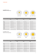
INTRODUCTION PrevaLED® Core Z2 – CRI 90: Six lumen packages 800 lm, 1500 lm 2000 lm 3000 lm, 4000 lm, 5000 lm PrevaLED® Core Z2 – CRI 90: Six lumen packages 2700 K 3000 K 3500 K 4000 K 800 lm LEP-800-927-C-Z2 LEP-800-930-C-Z2 LEP-800-935-C-Z2 LEP-800-940-C-Z2 1500 lm LEP-1500-927-C-Z2 LEP-1500-930-C-Z2 LEP-1500-935-C-Z2 LEP-1500-940-C-Z2 2000 lm LEP-2000-927-C-Z2 LEP-2000-930-C-Z2 LEP-2000-935-C-Z2 LEP-2000-940-C-Z2 3000 lm LEP-3000-927-C-Z2 LEP-3000-930-C-Z2 LEP-3000-935-C-Z2 LE
INTRODUCTION 1.2. System information 1.2.1. Nomenclature and marking The PrevaLED® family follows a consistent naming convention for identifying key parameters of the LED module and the power supply.
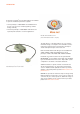
INTRODUCTION 1.2.2. Technical data 1.2.3. Accessories Technical data product family PrevaLED® Core Z2: For current data, please see the PrevaLED® datasheet at www.osram.com/prevaled-core. Cable kit The cable is required for contacting and connecting the individual PrevaLED® Core Z2 LED module with the power supply. It ensures a flexible and safe connection. This cable kit is approved according to UL (Underwriters Laboratories).
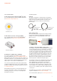
OPTICAL CONSIDERATIONS 2. Optical considerations Chip-on-board-design (CoB) So-called chip-on-board (CoB) light sources without housing and with high-performance chips set very closely next to each other have proven to be especially advantageous. Due to the large amount of applied chips, the size of the light source is flexible and scalable.
OPTICAL CONSIDERATIONS 2.1.1. Reflector design OSRAM provides mechanical (3D files) and optical simulation data (ray files) to support customized reflector designs. These data are available upon request through your sales partner or for public download at: www.osram.com/prevaled-core.
OPTICAL CONSIDERATIONS 2.1.2. Reflector mounting The LED modules have a clearly defined optical contact area (OCA) which provides a defined surface for attaching the reflector. In this configuration, the mounting and mechanical support of the reflector must be ensured by the luminaire body or by suitable structures for reflector mounting.
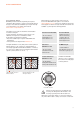
OPTICAL CONSIDERATIONS 2.2. Luminous flux and color stability Depending on the type of the LED module, the nominal CCT is 2700 K, 3000 K, 3500 or 4000 K, respectively. Depending on the variant, PrevaLED® Core Z2 modules provide a module-to-module color variation of less than 3 threshold value units (MacAdams steps) on the Planckian locus around this color target. These threshold value units can be shown within the ANSI (American National Standards Institute) norm in the following way: 2.3.
ELECTRICAL CONSIDERATIONS 3. Electrical considerations 3.1. Safety requirements All OPTOTRONIC® OTp devices intended for operating PrevaLED® Core LED modules are SELV*-equivalent devices with an output voltage of < 120 VDC. The design of the LED modules ensures that the requirements of IEC 62031 for LED modules are met. The chips on the LED module do not need to be covered in order to fulfill the requirements of IEC 62031.
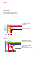
ELECTRICAL CONSIDERATIONS 3.3. Wiring in class I and class II luminaires Depending on the design of the luminaire according to class I or class II requirements, a protective earth connection can be established for the OPTOTRONIC® ECG. The functional earth (equipotential connection) may be connected to the ECG to improve EMI behavior. For these requirements, see the illustrations below. Since the power supplies are SELV-equivalent, no additional electrical insulation has to be provided for the LED module.
ELECTRICAL CONSIDERATIONS 3.5. Electrostatic safety measures In order to safely handle components susceptible to electrostatic discharge (ESD), an adjusted production environment is necessary. This is specified in IEC 61340-5-1 (“Electrostatics – Part 5-1: Protection of electronic devices from electrostatic phenomena – General requirements”). 3.6. Inrush current limitation Electronic drivers are subject of a certain inrush current.
THERMAL CONSIDERATIONS 4. Thermal considerations The proper thermal design of an LED luminaire is critical for achieving the best performance and ensuring the long lifetime of all components. Because the PrevaLED® Core Z2 ensures high efficiencies, only a partial amount of the introduced electrical power still has to be dissipated through the back of the light engine (see also: 1.2.2. Technical data (p. 7)). Depending on the application and the chosen LED module, passive cooling can be sufficient.
THERMAL CONSIDERATIONS 4.2. Heat sink Basically, the heat sink has to fulfill two tasks: Thermal conduction resistance (Rth) formula: a) Heat spreading through heat conduction The task here is to spread the heat as uniformly as possible from the contact surface of the LED module through the heat sink material and into the cooling fins. In this respect, the thermal conductivity and the material cross sections of the heat sink play a decisive role (cf. the thermal conductivities table below).
THERMAL CONSIDERATIONS For necessary heat transfer and good cooling, the surface of the applied heat sink material, with regard to heat emission, must be considered. In order to achieve very good radiation behavior to the ambient space, it can be advantageous to use heat sinks with a matt black finish. Thermal interface point (Tc point) Within typical applications such as downlights in recessed ceilings, it can be an advantage to use black anodized heat sinks.
THERMAL CONSIDERATIONS Recommended thermocouples Description Temperature [°C] Length [mm] Thermal probe -10…+100 2000 cable Adhesive foil probe -50…+250 1000 wire All figures in mm 4.4. Thermal simulation Using a computer, matching heat sink housing forms and occurring maximum temperatures can be calculated by means of numerical heat simulation. Thermal model description: PrevaLED® Core Z2 Two thermo simulation examples: T heat sink: 46…49 °C T ambient: 25 °C Surface area ~ 0.
THERMAL CONSIDERATIONS 4.5. ECG thermal considerations The installation of the ECG must ensure that the maximum temperature at the Tc is not exceeded. Further details on thermal considerations for OPTOTRONIC® devices can be found in the technical guide for OPTOTRONIC®, available at: www.osram.com/optotronic. 4.6. Thermal management and lifetime The PrevaLED® Core Z2 has a lifetime of 50,000 h (L70B50*).
THERMAL CONSIDERATIONS The thermal test engine (TTE) for the determination of thermal resistance: With the TTE according to Zhaga specification, the introduction of the heat output into an existing luminaire can be simulated. To do so, the following work steps need to be taken: 1. Installation of the TTE with thermal interface material (TIM) into the luminaire prototype to be measured 2. Introduction of different heat outputs PTTE (e.g. in 10-W steps) 3.
MECHANICAL CONSIDERATIONS 5. Mechanical considerations 5.1. LED module dimensions This schematic drawing contains further details on the dimensions of available PrevaLED® Core Z2 LED modules. For 3D files, LES and OCA categories, see the datasheet at: www.osram.com/prevaled-core. These 3D files in different formats may be used for the construction of luminaires. 5.2.
MECHANICAL CONSIDERATIONS 5.3. ECG dimensions Detailed mechanical drawings and 3D files are available at our website. Depending on the thermal interface material and contact surface conditions, the recommended screwing torque can be between 0.4 and 0.6 Nm. A higher torque level does not necessarily lead to significantly better heat transfer, but may lead to damage of the LED module. The recommended counter sink diameter of the mounting holes for good thermal performance should be 3.5 mm max.
ASSEMBLY IN A REFERENCE LUMINAIRE 6. Assembly in a reference luminaire To demonstrate the light engine concept and the design of a luminaire, the following pages will lead you through an exemplary assembly of a reference luminaire, using the 2000-lm PrevaLED® light engine.
ASSEMBLY IN A REFERENCE LUMINAIRE 6.2. Wiring and reflector/cover The corresponding cable kit can be used to connect the LED module to the power supply. To get the connector easily into the housing, we recommend a through hole with a minimum diameter of 10 mm. Once the LED module is connected, the reflector can be attached to the housing and the diffuse cover can be placed on top of the luminaire. 9 10 11 12 13 14 15 16 17 18 Both components have to be properly centered above the LED module. 6.3.
NORMS AND STANDARDS 7. Norms and standards 7.1.
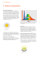
NORMS AND STANDARDS 7.3. Photobiological safety Looking directly at high-performance light sources can (just approximate classification of safety classes like looking directly at the sun) be a hazard to the retina of the human eye. This is why the PrevaLED® LED modules have been tested regarding the risk group definition within the framework of EN 62471:2008. According to EN 62471-1, PrevaLED® Core LED modules have to be classified in risk group 1.
OSRAM GmbH Head Office Marcel-Breuer-Strasse 6 80807 Munich Germany Phone +49 (0)89-6213-0 Fax +49 (0)89-6213-20 20 www.osram.com 06/13 Subject to change without notice. Errors and omission excepted. www.osram.com/prevaled-core www.osram.