www.osram.
PrevaLED ® Core Z3 LED modules | Contents Contents 1 Introduction 03 5 Lifetime and thermal behavior 17 1.1 System overview 03 6.1 Flux as a function of temperature 17 1.2 Nomenclature 03 6.2 Lifetime 17 2 Optical considerations 04 6 Mechanical considerations 18 2.1 Light distribution 04 6.1 Outline drawing 18 2.2 Refl ector design 04 6.2 3D drawing 18 2.3 Refl ector mounting 06 6.3 Mechanical protection of the PrevaLED ® Core Z3 2.4 Color temperature 06 2.
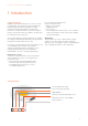
PrevaLED ® Core Z3 LED modules | Introduction 1 Introduction 1.1 System overview Building an LED-based luminaire poses a new set of technical challenges, among them new optical requirements, providing adequate thermal management for stable operation and lastly dealing with the ever-improving performance of LEDs. Nevertheless, LED technology also provides an unknown wealth of possibilities, opening up unprecedented levels of performance.
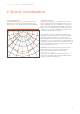
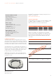
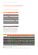
PrevaLED ® Core Z3 LED modules | Optical considerations 2 Optical considerations 2.1 Light distribution The light distribution of the LED module is shown in the graph below. PrevaLED® Core Z3 LED modules create a beam angle of 115° FWHM (full width at half maximum). C 0° The PrevaLED® Core Z3 is equipped with a surface that emits light evenly and makes the use of diffuser materials unnecessary due to its high level of homogeneity.
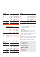
PrevaLED ® Core Z3 LED modules | Optical considerations PrevaLED® Core Z3, 5000 lm, LES 23, OCA D* PrevaLED® Core Z3, 1100 lm, LES 9, OCA A* Reflector Reflector output diameter [mm] 40 50 60 Reflector output diameter [mm] 70 height [mm] 80 100 120 140 height [mm] 50 12°; 14000 cd; 10°; 17000 cd; 40 100 14°; 38000 cd; 12°; 48000 cd; 89 %; 3400 lx; 90 %; 4400 lx; 80 %; 9500 lx; 81 %; 12100 lx; 12.5 cd/lm 15.9 cd/lm 7.6 cd/lm 9.
PrevaLED ® Core Z3 LED modules | Optical considerations Alux·Luxar GmbH & Co. KG Schneiderstrasse 76 40764 Langenfeld, Germany +49 2173 279 0 sales@alux-luxar.de www.alux-luxar.de Almeco S.p.A. Via della Liberazione, 15 20098 San Giuliano, Milanese (Mi), Italy +39 02 988963 1 info.it@almecogroup.com www.almecogroup.com Nata Lighting Co., Ltd. 380 Jinou Road, Gaoxin Zone Jiangmen City, Guangdong, China +86 750 377 0000 info@nata.cn www.nata.cn 2.
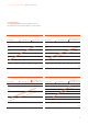
PrevaLED ® Core Z3 LED modules | Optical considerations 2.5 Color rendering PrevaLED® Core Z3 LED modules provide a color rendering index (CRI) of either > 80 or >90. The table below shows the individual Ra values from R1 to R16 for the available color temperatures.
PrevaLED ® Core Z3 LED modules | Optical considerations 2.7 Flux behavior The following diagrams show the luminous flux over the operating current for all PrevaLED® Core Z3 modules.
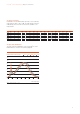
PrevaLED ® Core Z3 LED modules | Electrical considerations 3 Electrical considerations 3.1 Forward voltage as a function of temperature 1100 lm 2000 lm 3000 lm 5000 lm Relative forward voltage normalized at 65 °C [%] 101.5 101.0 100.5 100.0 99.5 99.0 98.5 98.0 0 20 40 60 80 100 120 Case temperature tc [°C] 3.2 Electronic control gear/LED module combination PrevaLED® Core Z3 LED modules can either be used with constant-current control gears or in combination with OSRAM OTi control gears.
PrevaLED ® Core Z3 LED modules | Electrical considerations 3.3 Wiring The input clamps used in the PrevaLED® Core Z3 can handle solid wires with a cross-section of 0.5–1.0 mm2 (AWG 21-17). Example: H05V-U 1x 0.5 mm2 Wire preparation Please note: — The connector is designed for three “poke-in” and release cycles. — The installation of LED modules needs to be carried out in compliance with all applicable electrical and safety standards. Only qualified personnel should be allowed to perform installations.
PrevaLED ® Core Z3 LED modules | Electrical considerations Connect and release Connect Plug wire directly Release 1 Use a very slim screwdriver and push gently into the release hole 2 Note: Push in the screwdriver below the release spring.
PrevaLED ® Core Z3 LED modules | Electrical considerations 3.4 OTi electronic control gear series If you use the PrevaLED® Core Z3 series in combination with the OSRAM OTi control gear series, you will get the best results and the full functionality of the LED module. 3.6 OTe electronic control gear series If you like to use the OSRAM OTe series, please connect the terminal LED+ to the module and select the desired current by connecting it to only one of the output terminals 21, 22 or 23.
PrevaLED ® Core Z3 LED modules | Electrical considerations The following values result for the modules which are possible to drive with LCTS drivers: Module Example of wiring: I [mA] R [Ohm] PL-CORE-2000-830 400 22419 PL-CORE-2000-840 385 21715 PL-CORE-2000-930 490 26642 PL-CORE-3000-830 590 31335 PL-CORE-3000-840 575 30631 PL-CORE-3000-930 730 Use DIP switch for 700 mA. Module is under-driven. PL-CORE-5000-830 950 Use DIP switch for 700 mA. Module is under-driven.
PrevaLED ® Core Z3 LED modules | Thermal considerations 4 Thermal considerations The proper thermal design of an LED luminaire is critical for achieving the best performance and ensuring the longest lifetime of all components. Due to the high efficacy of PrevaLED® Core Z3 LED modules, only a partial amount of the introduced electrical power has to be dissipated through the back of the LED module. The thermal power that has to be dissipated for PrevaLED® Core Z3 LED modules is given below. 4.
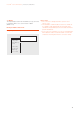
PrevaLED ® Core Z3 LED modules | Thermal considerations Please note: A thermal design must always be confirmed by performing a thermal measurement in steady-state condition.The whole area of the PCB must be in contact with solid material of the heat sink. In the following, you find two examples of how to cool a PrevaLED® Core Z3 LED module. Location of the tc point Example 1: LED module: PL-CORE 1100-827 Heat sink: Fischer SK572 height: 37.
PrevaLED ® Core Z3 LED modules | Thermal considerations To measure the temperature and to ensure a good thermal coupling between the LED module and the heat sink, drill a hole into the heat sink and push the thermocouple through the heat sink. To ensure a direct contact between the thermocouple and the PCB, it is recommended to glue the thermocouple onto the PCB. You can, for example, use an acrylic adhesive (e.g. type Loctite 3751).
PrevaLED ® Core Z3 LED modules | Lifetime and thermal behavior 5 Lifetime and thermal behavior 5.1 Flux as a function of temperature The following diagram shows the behavior of the flux output over the tc point temperature for Prevaled Core Z3. PL-CORE-2000 lm/3000 lm-Z3 Relative luminous intensity normalized at 65 °C [%] 108 106 104 102 100 98 96 94 92 25 45 65 85 Case temperature tc [°C] 5.
PrevaLED ® Core Z3 LED modules | Mechanical considerations 6 Mechanical considerations The following schematic drawing provides further details on the dimensions of PrevaLED® Core Z3 LED modules. For 3D files of the LED modules, please go to: www.osram.com. 6.1 Outline drawing 6.3 Mechanical protection of the PrevaLED ® Core Z3 LED module The housing of a PrevaLED® Core Z3 LED module should not be exposed to strong mechanical stress. Please apply force only to the dedicated mounting positions.
PrevaLED ® Core Z3 LED modules | Norms and standards 7 Norms and standards Safety: Photobiological safety: Risk group: Electromagnetic compatibility: Ingress protection: Flammability of plastics: Approvals: IEC/EN 62031 IEC/EN 60598-1 IEC/EN 62471 1 CISPR 15 IEC/EN 61547 IEC/EN 61000-3-2 IEC/EN 61000-3-3 EN 55015 IP10 UL8750 Class 2/UL 94 850 °C glow wire test CE,UL 19
12/13 OSRAM S-GI MK EM Subject to change without notice. Errors and omissions excepted. www.osram.com/prevaled-core OSRAM GmbH Head Office: Marcel-Breuer-Strasse 6 80807 Munich, Germany Phone +49 (0)89-6213-0 Fax +49 (0)89-6213-20 20 www.osram.