www.osram.com www.osram.de June 2009 QUICKTRONIC® DALI/DIM Technical Guide. Dimmable Electronic Control Gears for Fluorescent Lamps. • DALI/1…10 V Basics • Product Overview and Features • Installation and Operation Instructions DALI_Cover_E.indd 2 05.06.
Contents 1 1.1 1.1.1 1.1.2 1.1.3 1.1.4 Introduction ................................................................. 4 Dimmable lighting systems .............................................. 4 Economy......................................................................... 4 Lighting comfort .............................................................. 5 Reliability/Safety .............................................................. 6 The right control unit for every application ......................
.2.5 3.2.6 3.2.6.1 3.2.6.2 3.2.7 3.3 3.3.1 3.3.2 3.3.4 3.8.1 3.8.2 3.8.3 3.8.4 3.9 3.9.1 3.9.2 Operating modes with TouchDIM .................................. 33 Asynchronism/Automation of the system....................... 36 Prevention/remedying of asynchronism ......................... 36 Synchronization............................................................. 36 Behavior after mains voltage failure ............................... 37 OSRAM DALI ECGs in emergency lighting applications ....
7 Tender documents ..................................................... 68 8 8.1 8.1.1 8.1.2 8.1.3 8.1.4 8.1.5 8.1.6 8.2 8.2.1 Frequently asked questions (FAQ) ........................... 72 Part of DALI .................................................................. 72 TouchDIM ..................................................................... 72 DALI in general .............................................................. 73 DALI to 1…10 V converter ............................................
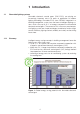
1 Introduction 1.1 Dimmable lighting systems Dimmable electronic control gears (DIM ECGs) are playing an increasingly important role in all areas of application of modern lighting technology. Dimmable ECGs from OSRAM, integrated in a building management system, form the heart of intelligent lighting systems which save up to 80 % of energy compared to conventional electronic control gears.
1.1.2 Lighting comfort Lighting situations at the touch of a button (lighting scenes), also with integrated presence detection and daylight/time-dependent control, increase lighting comfort.
1.1.3 Reliability/Safety Reliability and safety play a crucial role in the use of electronic control gear.
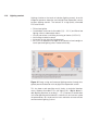
2 Overview of dimmable electronic control gears 2.1 Block diagrams of a digital/analog dimmable ECGs2 a) Digital dimmable ECG with DALI interface b) Analog dimmable ECG with 1…10 V interface Figure 3: EMC filters and safety shutdown are important elements of high-quality dimmable electronic control gears.
2.2 DALI in comparison to 1…10 V and EIB/LON What modern lighting technology needs is a system that is as flexible as it is simple, a system that focuses on room-based lighting control with just a few low-cost components, minimal wiring and a user-friendly operating concept. The lighting industry has therefore developed a new digital communication standard for lighting systems: DALI closes the gap between the former 1…10 V technology and complex bus systems.
special lines or cable penetrations. A 5 x 1.5 mm2 NYM cable, for example, can be used for the mains feed and DALI. 1…10 V DALI Potential-free control input Potential-free control input Two-wire line (with +/- polarity) Two-wire line (polarity-free) Dimming curve, luminous flux linear Dimming curve, optically linear (= logarithmic), matching the sensitivity of the eye Non-addressable • Wiring acc. to groups required Addressing possible: • Individual (max. 64 addresses) • In groups (max.
2.3 DALI installation & features 2.3.1 Simplified installation The installation of DALI is carried out with commercially available installation material for 230 V line voltage. The two wires of the five-wire cables (e.g. NYM 5 x 1.5 mm²) that are not needed can be used for the DALI interface - regardless of polarity. Thus, no separate bus cable is required! The ECG and control unit can be operated on different line voltage phases. 2.3.
2.3.6 No more switching relays The ECGs are switched on and off via the interface. The former external relays required for switching are therefore no longer needed. 2.3.7 Addressing is not essential DALI can also be used without any addressing (groups or individual addresses). A method known as broadcast mode is used here, which simply means that all control units are addressed together. 2.4 Installation and wiring instructions 2.4.
Note (acc. to DIN VDE 0100/11.85, T 520, Sect. 528.11): Cables or lines that are insulated for the maximum operating voltage must be used, or each conductor of a multi-wire cable/ line must be insulated for the next voltage appearing in the cable/line.
2.4.
2.4.3 Radio interference suppression of dimmable luminaires The use of dimmable ECG is only approved in luminaires of protection class I (PC I) as only here is adequate grounding assured. Note: When dimming, the operating frequency of the lamp and the lamp burning voltage increases at the same time which can lead to elevated leakage currents. Leakage currents emerging from the lamp always flow back into the ECG because the current circuit must be closed.
Notes: • Max. lamp cable length of the "hot end" (higher potential to ground): T5, T8: 1 m/T4: 0.
2.4.4 Operation of multiple ECGs in a luminaire If several dimmable ECGs are operated in a luminaire, there can be interference effects and hence to flickering, jerky dimming or even to shutdown of the ECGs if they have not been correctly installed. The cause for this are inductions between the lamp current circuits of several ECGs: If a lamp running at 100 % transfers just 1 % of its current into the neighboring lamp dimmed to 1 %, this represents a fault of 100 %.
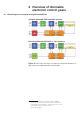
The better these recommendations are implemented, the more stable is the light at the lowest dimmer setting, even with a very small lamp spacing – and, hence, the full temperature range of the ECGs can be used. • In the "worst case" twist the cables of the heating circuits together, hence ensuring they lie close together. With 1-lamp ECGs these are the 21-22 and 26-27 cables, with 2-lamp ECGs; 21-22 and 21-23, 24-25 and 26-27.
Figure 7: Three 2-lamp ECGs Correct: Wrong: The lamp lines are laid close to the respective lamps. The overlapping of the three right lamp current circuits is minimized. The lamp lines of all ECGs are laid together, also overlapping lamp current circuits are formed in this way. Note: T5 florescent lamps must be used so that the lamp stamps are on the same side. The lamp stamp must be underneath (Cold Spot) in the upright burning position.
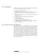
2.5.2 DALI topology The DALI ECGs are wired in parallel to each other and groups are not taken into consideration. Star configurations are also possible. Ring wiring is not permitted (indicated by X in the diagram). There is also no need for terminating resistors on the communication cable. Figure 8: DALI topology 2.5.3 DALI parameters in the ECG The following data can be stored in the DALI ECGs when a DALI system is started up: • Group assignment of the DALI ECG (max.
2.5.4 Requirements to be met by the transmission cable When selecting a cable make sure that the voltage drop on the line does not exceed 2 V at 250 mA. As with 1…10 V systems, the power supply and control line can be run in the same cable. This means, for example, a 5-core NYM cable can be used to connect the DALI ECG without any problems. The maximum permitted total length of cable between the controller and the connected ECG is 300 m. Cross section of the power cable: A = L x I x 0.
Controllers and electronic control gears may be connected to different power supply phases.
2.6 DALI data transfer With DALI, data telegrams are produced by short-circuiting and releasing the line in order to generate the corresponding "low" or "high" logic states. This may be caused by either the ECG or by the controller. In the event of a short-circuit the current is limited by the interface supply to 250 mA. In the idle state (no data transfer) approx. 16 VDC is on the ECG. The following figures illustrate data transfer via DALI: Sender unit Receiver unit Undefined 22.5 V max. 20.5 V max.
“Biphase" databit coded with value “1" “Biphase" databit coded with value “0" High level (= idle state) Voltage Low level Incoming data telegram ECG response Current consumption < 250 mA (active limit by the DALI supply) Current consumption < 2 mA Current Figure 12: Data transfer using the Manchester code on the DALI line Data is transferred using the Manchester code. The signal edges in the middle of the bit carry the information here.
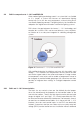
The dependency of the relative luminous flux X (n) on the digital 8-bit value n is described by the following correlation: X (n) = 10 n −1 253 3 X (n) − X (n + 1) = 2,8 % = Const . X ( n) ! This results in the following graphical association: Figure 13: DALI dimming curve 2.7.
2.8 Features of the digital interface • IEC 62386 – This allows the combination of units from different manufacturers. A special feature to be noted is that the DALI manufacturers represented in the AG DALI.6 test their units together in order to guarantee high functional security.
• Dimming range 1 %…100 % (the lower limit depends on the lamp and manufacturer). The progression of the characteristic is standardized and adapted to the sensitivity of the eye (logarithmic characteristic). Because of the standardization, a similar sense of brightness is achieved when using control units from different manufacturers • Programmable dimming times – special settings such as light change speeds (e.g.
Note: Due to the characteristics of the 1…10 V interface, the following must be noted: • All control lines of an ECG installation must be connected with the right polarity (+/-) • The control line is voltage-insulated from the mains line but there is no safety extra-low voltage (SELV).
luminous flux in % The 1…10 V dimming curve The 1…10 V interface is defined in IEC 60929. In the control voltage range of 3 V to 10 V there is a largely linear relationship to the relative luminous flux. In the 1…10 V interface, a logarithmic response (like the DALI units) is adjusted by a logarithmic potentiometer. Control voltage in V Figure 14: The 1…10 V characteristic: Luminous flux against control voltage The control current in the 1…10 V interface drops with increasing control voltage.
3 Additional characteristics of dimmable electronic control gears from OSRAM9 3.1 OSRAM DALI/1…10 V ECG: Added-value through intelligent features • Automatic lamp detection through intelligent multi-lamp operation (reduction of the ECG type variety) Lamps of the same length and different powers can be operated on an ECG.
• EoL shutdown after Test 2 Asymmetric power test for detecting defective lamp electrodes or high-impedance lamp paths due to leaks in the glass tube • Chip ID (CIN = Chip Identification Number, serial number) for simple system installation ! OSRAM DALI Luminaire Tool (DLT): Address assignment via CIN possible • EEPROM for backing up settings/parameters even if the mains supply fails • Lamp replacement without mains reset (automatic lamp reactivation after lamp replacement) [including HF DIM] • DC operation
3.2.1 Wiring and line compensation • The line lengths between buttons and the farthest away DALI ECG should not be longer than 25 meters. Where line lengths over 25 meters are required, compensation methods (bell transformer, resistor) must be used • Do not use more than 6 DALI ECGs in one TouchDIM application (up to 6 ECG can be controlled by one switch, the number of operating points is limited to 2) • Different lamp families should not be mixed because of the different preheating times (e.g.
Note: • Only use switches without control lamp and with 230 V normallyclosed contact as the permanent current through the glow lamp can lead to malfunctions • TouchDIM is not part of the DALI standard (IEC 62386), but rather an additional OSRAM function 3.2.2 Operating parameters for TouchDIM To operate the TouchDIM, AC voltages of 10…230 V (RMS) at a frequency of 46…66 Hz can be used – there is no DC voltage allowed. 3.2.
The option of connecting a conventional resistor is also available (150 kΩ, 1 W) for compensating interferences (damping of the line) between the phase and neutral conductor. The resistor can also remain in the control line during DALI operation which is not affected (< 2 mW power loss). Max. 50 m total line length for compensation of the connection cable L N R: 150kOhm, 1W Figure 19: Compensation of the connection line by a resistor (150 kΩ, 1 W)12 3.2.
Mode 2: The electronic control gear switches on with the dimming value (preset value) last stored by double-clicking.
The following table once again explains the behavior of the ECG for different switching actions: Action TouchDIM Short press (status: switched off) Short press (status: switched on) TDI Mode I: switches on to last value before switch-off TDI Mode II: switches on to last double-click value Switch-off and store value for next switch-on in TDI Mode I Long press (status: switched off) Switch on and fade from min upwards Dimming as long as button is pressed Long press (status: switched on) Dimming fades
3.2.6 Asynchronism/Automation of the system The increased use of DALI ECGs in button operation shows again and again that in systems with • not completely sinusoidal supply voltage (e.g. electronic dimmer on the same mains supply), • excessively long line lengths or • high DALI ECG count (more than 6 ECGs per TouchDIM application) increasing results in asynchronism of the connected DALI ECGs.
3.2.7 Behavior after mains voltage failure If the luminaire is disconnected from the mains, the ECG saves all set values. If the light value has been changed before being switched off, this value is restored, i.e. after a voltage loss, exactly the last status is reestablished (instant switch-on to the previous present luminous flux, no "intermediate path" above 100 % luminous flux and subsequent dimming).
For emergency lighting/voltage loss13 in the DALI controllers two values can be configured/programmed separately for each unit (e.g. using the OSRAM DALI Luminaire Tool DLT).
The use of OSRAM DALI electronic control gear in emergency lighting management is explained in the following. General UV lighting L N General luminaire lighting Phase control L N IN IN 3 DALI controller ~ ~ D D DA DA OSRAM DALI ECG 4 1 2 3 4 X . Dimming button U U 2 Emergency luminaire lighting D1 D2 ~ ~ Monitoring module 0 0 ZB-S L D1 max. 1m D2 DA DA OSRAM DALI ECG 1 1 2 3 4 X .
3.3.2 Mains failure at the main distributor (HV) The central battery system (CB) provides DC supply voltage. The external DALI controller (3) is ignored, the ECG is dimmed to a previously defined value by the monitoring module (1), which is DC compatible, via a DALI instruction set. The emergency lighting level is pre-specified. OSRAM DALI ECGs (1) can communicate DALI and, hence, be individually dimmed by applying a DC voltage supply. 3.3.
The functions of the OSRAM DLT are: • Luminaire function test (for production) • Reading of all DALI parameters (e.g. in the event of complaints) • Preprogramming of all DALI parameters (e.g. for projects) • Reading and printing of the unique OSRAM operating unit address (OSRAM-ID ! CIN (Chip Identification Number)) of each QUICKTRONIC INTELLIGENT ECG and printing on barcode (128-bit) for simplified system commissioning o Placing the label on the luminaire o Max.
Figure 23: DALI parameters that can be changed by the DLT 3.5 Basic switching actions of 1…10 V control gear The simplest type of light control can be realized via an appropriate logarithmically-dimensioned potentiometer (available from the electrical trade). Because the control power of the OSRAM DIM ECG is generated by the ECG itself, the resistance value is dependent on the number n of the connected ECG.
The following figure illustrates control via a potentiometer: N L N L DIMM-ECG – + N L On/Off switch DIMM-ECG – + N L – + Potentiometer R = 100 kΩ log. n L N 1 2 3 4 1 2 3 4 Lamp Lamp 1 DIMM-ECG 2 3 Lamp 4 – + n: Number of connected ECGs Figure 24: Potentiometer control of the 1…10 V interface 3.5.1 1…10 V: Staircase operating modes As a basic principle, frequent switching is not ideal for fluorescent lamps and compact fluorescent lamps.
Figure 25: Stairwell lighting timer switch b) Stairwell lighting timer switch and motion detector Because the button engages the line voltage (L), it can be replaced by a motion detector. Parallel switching with the switch is also possible. Because the switch-on time is set on the stairwell lighting time switch, the switch-on time of the motion detector can be set to a minimum.
3.5.1.2 Control via analog output The external control with an analog output 0…10 V (e.g. PC card) is basically possible. This control module must be capable of taking the current supplied by the ECG in the control line and of reducing the control voltage to at least 1 V.
3.5.1.4 Control via instabus EIB Dimmable ECG with 1…10 V interface can be easily integrated in installations with the instabus EIB building control system. The link between EIB and the dimmable lighting system is a switching/dimming actuator. A switching/dimming actuator is required for each lighting group. The digital bus signal is converted by the switching/dimming actuator into the analog 1…10 V control voltage for OSRAM DIM ECGs. The ECG is switched on/off by an integrated relay contact.
The temperature controller can be a room temperature controller for heating control, for example. The switching temperature (e.g. 0 °C) should be as precisely adjustable as possible. The switch must be a closer, i.e. must be closed at high temperatures. Such appliances are offered with a bimetal contact (e.g. 2NR9 090-1, power supply not required) or with a temperature sensor (e.g. 2NR9 078, power supply required).
b) Lower limit An effective lower limit can be realized by a series connection of 2 control units. The sum of the two units is effective. With one unit, the default control voltage of the other unit cannot be undercut. Attention: In a series connection, two control units (e.g. DIM MCU) is the smallest achievable control voltage approx. 2 V (~= 4 % luminous flux) connections must be realized according to the diagram. Figure 30: Lower limit of the control voltage 3.6.
Figure 31: Emergency lighting with 1…10 V DIM ECG It must be noted that some accessory components (e.g. DIM SA signal amplifiers) are not approved for battery operation. Therefore, it is important to make sure that these components are never connected to DC voltage. In this case the signal amplifier, for example, constitutes a fixed resistance that is connected to the control line. The dimmer setting of an ECG is then around 20 %, and accordingly higher for more than one. 3.
3.7.1 Inserting and releasing the connection cables Manual cabling of the insulation piercing connection device (above) with the WAGO insertion tool, e.g. order number: 206-831 Figure 32: Wago insertion tool Detachment of the contacts (below) with the WAGO 206-830 extraction tool. 1. Insert extraction tool into the line guide above the line 2. Pull out line Figure 33: Wago extraction tool Alternatively, the plug contact can be released by simultaneous twisting and pulling.
3.7.2 Cable cross sections Single-wire conductor ² Multi-wire conductor max. 0.75 mm² Insulation displacement contact (IDC contact) max. 0.5 mm Plug contact 0.5…1.0 mm² 0.5…1.0 mm² (with wire-end sleeve) Push terminal 0.5…1.5 mm² 0.5…1.5 mm² (with wire-end sleeve) Table 6: Typical cable cross sections of plug and insulation displacement contacts 3.7.3 Basic insulation IEC 61347 demands basic insulation between the control circuit and mains supply for control inputs.
3.8 Temperature response of dimmable ECGs from OSRAM Permissible standard values for minimum ambient light temperatures: Lamp type Min. temperature at 1 % (3 % CFL) dimmer setting T8/26 mm lamp*** -20 °C* 1 %* +10 °C +10 °C 60 %**** 50 % 30 % 30 % +10 °C** 50 % T5/16 mm lamp* HE 14…35 HO 49 HO 24…80 DULUX L* DULUX D/E, T/E, FC Min.
Note: • Limits the tc temperature to < 80 °C (depending on installation condition), but never switches the ECG due to excessive temperature • Thermally problematic luminaires do not necessarily become standard conformant devices, even with these ECGs • Power reduction is carried out up to 50 % of full load operation Functionality The ECG measures the ECG temperature once per minute.
Ta [°C] Rel.
Why are the light losses so small due to the temperature limitation? Assuming a luminaire whose inside temperature (= lamp ambient temperature) is to be lowered from 65 °C to 55 °C. A reduction of the system power by 20 % is required for this. The diagram shows the Φ(T) curves of T5 lamps for 100 % and 80 % system power. During the transition from the 100 % curve to the 80 % curve and the lowering of the lamp ambient temperature by 10 °C, the luminous flux remains roughly the same.
3.8.2 Color temperature Between the maximum and minimum luminous flux of the lamp the color temperature of the lamp changes – in a DULUX L this is approx. 150 Kelvin. Due to the great difference in luminance density, the color difference appears to be visually considerably greater. As a result, the subjective perception of the human eye does not reflect the objective color temperature change.
3.8.4 Functional test of luminaires The dimmable QTi family from OSRAM (DALI and 1…10 V) gives in the luminaire test (with 10 Ω filaments) the following power per lamp: 1-lamp/2-lamp (T5 and T8): 32 Watts 3-lamp/4-lamp (T5 and T8): 16 Watts This function is independent of the deployment of the actual lamp. For special applications/luminaires, the filament detection can be switched off – details on request.
D T/E 32 W IN PLUS D T/E 42 W IN PLUS D T/E 57 W IN PLUS DL 80 W CONSTANT DL 55 W CONSTANT DL 40 W CONSTANT HO 80 W CONSTANT HO 54 W CONSTANT D T/E 26 W IN PLUS QTi DALI / QTi (1…10 V) 1x14/24 DIM QTi DALI / QTi (1…10 V) 1x21/39 DIM QTi DALI / QTi (1…10 V) 1x28/54 DIM QTi DALI / QTi (1…10 V) 1x35/49/80 DIM QTi DALI / QTi (1…10 V) 2x14/24 DIM QTi DALI / QTi (1…10 V) 2x21/39 DIM QTi DALI / QTi (1…10 V) 2x28/54 DIM QTi DALI / QTi (1…10 V) 2x35/49/80 DIM QTi DALI / QTi (1…10 V) 3x14/24 DIM QTi DALI / Q
Power Boost HO24 CONSTANT 10 9 ECG power [W] Rel.
(T) curves of T5 lamps 100 Relative luminous flux [%] 90 80 70 60 50 40 30 20 10 0 -10 0 10 20 30 40 50 60 70 80 Lamp ambient [°C] ----- 90% T5 Standard T5 C ONSTAN T of dimmable standard ECG T5 C ONSTAN T of QTI DALI/DIM Figure 43: QTi DALI/DIM: More luminous flux over an expanded temperature range Lamp type Min. temperature at 1 % (3 % CFL) dimmer setting Min.
3.9.2 Benefits of amalgam technology Note: Dimming of amalgam lamps is also suitable for outdoor applications. Sufficient attention should be paid that the ECG is protected against external influences (IP67).
Note: • Amalgam and mercury lamps must never be mixed in multilamp ECGs because the power increase available in amalgam lamps would lead to a vigorous overshooting of the light in a mercury lamp. In addition, the synchronization in the lower dimming range would be poor.
4 System energy consumption and dimmer setting Because there is a largely linear relationship between the power consumption of the DALI/DIM systems (lamp and ECG) and the dimmer setting, the power consumption PN(d) can be calculated for each dimmer setting d (in percent) from the values PN100 % (100 % nominal power, PN = Power Nominal) and PN1 % (nominal power of 1 %) (depending on ECG lamp combination, available on request): Energy consumption (system) PN (d ) PN 1% PN 100% PN 1% v (d 99% 1%) 100 %
5 Dimming of compact fluorescent lamps DULUX T/E 26W (IN) FC 22W FC 40 W DULUX T/E 18W DULUX D/E 26W DULUX T/E 32W (IN) DULUX T/E 42W (IN) DULUX D/E 18W DULUX T/E 57W (IN) Figure 47: Range of lamps with an ECG, www.osram.com/qti With the new CFL MULTI lamp ECGs, DULUX T/E 18 W as well as T/E 57 W can be operated on one ECG. All 2-lamp downlights for 2x18, 2x26, 2x32 and 2x42 W can be fitted with only one 2-lamp QTi DIM ECG.
5.
Numerous applications in the downlight sector can be covered by one luminaire type in combination with the new QTi T/E DALI/DIM generation from OSRAM. Thus, for example, it is possible to design the lighting of a building with different room heights and different luminaire installation locations (e.g. corridors, foyers etc.) so they are simple and flexible to dim. Thus, several “lumen packages" are possible for each room. Due to optimized filament preheating, the lamp starts inside 0.
6 The Activity Group DALI (AG DALI) The “DALI" workgroup was set up in 1999 under the auspices of the ZVEI (the German Central Association of Electrical Engineering and the Electrical Industry) with the aim of establishing this new standard on the market. All the leading manufacturers of ECGs and controllers are represented in this Activity group so they can develop and market their products in accordance with the requirements of the DALI standard.
7 Tender documents QUICKTRONIC® INTELLIGENT DALI DIM for compact fluorescent lamps Ordering designation according to lamp type: QTi DALI-T/E … DIM • Intelligent ECG with DALI interface according to IEC 60929 • Compact fluorescent lamps, OSRAM DULUX® T/E 18, 26, 32, 42 W and OSRAM DULUX® T/E IN 26, 32, 42 (57) W (amalgam lamps) from 3 % to 100 % can be dimmed without any restriction • Warm start of the lamp inside 0.
through intelligent power reduction at high tc temperatures • 5-year system+ guarantee: For every ECG that failed due to a material or production fault, a replacement is available • CELMA energy classification EEI = A1 • Maximum energy efficiency thanks to cut-off technology • EoL shutdown acc. to EN/IEC 61347-2-3 Section 17 • For use in emergency lighting systems acc.
QUICKTRONIC® INTELLIGENT DIM (1…10 V) for compact fluorescent lamps Ordering designation for each type of lamp: QTi-T/E…DIM • Intelligent ECG with 1…10 V interface acc. to IEC 60929 • OSRAM DULUX compact fluorescent lamps® T/E 18, 26, 32, 42 W and OSRAM DULUX® T/E IN 26, 32, 42 (57) W (amalgam lamps) unrestrictedly dimmable from 3 % to 100 % • Warm start of the lamp inside 0.6 seconds without switch-on flash • Service life: 50,000 h at maximum thermal load (tc = 75 °C, max.
• EoL shutdown acc. to EN/IEC 61347-2-3 Section 17 • For use in emergency lighting systems acc. to EN 50172 / DIN VDE 0108-100 • Test mark: ENEC, VDE, EMC • EN 60929, EN 61347-2-3, EN 55015, EN 61000-3-2, EN 61547, EN 61000-3-3 QUICKTRONIC® INTELLIGENT DIM (1…10 V) for T8/Ø 26 mm fluorescent lamps Ordering designation for each type of lamp: QTi … DIM • Intelligent ECG with 1…10 V interface acc.
8 8.1 DALI part 8.1.1 TouchDIM Frequently asked questions (FAQ) • Can the TouchDIM function and a DALI controller be used at the same time? No. Either a DALI controller or the TouchDIM function! TouchDIM and DALI operation are mutually exclusive. • How do the ECGs behave after a mains voltage failure? The DALI ECG of the QTi series automatically reestablish the previous status. Both the switching status (on/off) and the dimmer setting are taken into account here.
• Can a TouchDIM system be upgraded with a DALI controller? Yes, an upgrade is possible at any time. Changeover of the DALI ECGs from TouchDIM to DALI takes place automatically after a power outage on the ECG when the first DALI command is sent. TouchDIM and DALI control cannot be used at the same time! • Can the motion function of the TouchDIM sensor be switched off (holiday mode)? Yes, the so-called "holiday mode" prevents the lighting system being switched on by the motion sensor.
• Can a DALI ECG belong to more than one group at the same time? Yes. Each DALI controller can belong to up to 16 groups. • Where are the data for the group assignments and light scene values stored? They are stored directly in the internal EEPROM of the ECG. • Are the data in the ECG lost if there is a power failure? No, the data are permanently stored in the ECG. They are retained even if the power failure is prolonged.
• What insulation is required for the DALI control line? The DALI control line must be approved for mains voltage (as in the case of the 1…10 V interface). • Can existing 1…10 V control lines be used? Yes, provided they are rated for mains voltage. • How long can a control line be? A maximum of 300 m between the controller and the furthest connected DALI unit. • Can control and power cables be laid together? Yes, a 5 x 1.5 mm2 NYM cable can be used, for example.
8.1.3 DALI to 1…10 V converter • Is it possible to switch and dim with DALI to 1…10 V converters? Yes, with the converter both are possible. • Can the converter also offer the TouchDim function? Yes, the converter behaves like a DALI ECG here in TouchDIMmode 1. • Why does the converter have characteristic changeover? So that it is possible to compensate for the different behaviours of incandescent lamps and fluorescent lamps.
2. The available daylight is sufficiently bright. Cover the sensor and observe the response of the luminaire. 3. The motion detection is deactivated for 30 s after the lighting system has been switched off manually. This time will only expire if there are no more people in the detection zone. • The luminaire is not regulating its the brightness to the setpoint value 1. After setting the brightness, you must press the button twice inside 30 s (to store the setpoint value).
• Can control and supply lines be laid together? Yes, control and supply lines can be laid together (VDE 0100 520 Section 528.11). The following points must be noted: • The lines used must comply with the maximum operating voltage that occurs. (VDE 0100/11.85, T520 Section 528.11) • When laying core lines in installation ducts or channels, only the conductor of a main current circuit, including the associated auxiliary circuits, may be laid.
8.2.1 Troubleshooting 1…10 V • Lamp does not burn with 100 % luminous flux The control line is not connected or not correctly connected to the control unit, or the control unit is not a sufficiently good current sink and, hence, cannot reduce the control voltage. Check the wiring. Check that the control voltage is reduced while dimming and, if necessary, install a parallel resistor in the control line.
9 9.1 Appendix Starting currents and max. number of ECGs in automatic cutouts Figure 51: Starting currents and max. number of ECGs in automatic cutouts (B characteristic), measurement at UN = 230 VAC 9.1.1 Minimum B/C characteristic triggering levels The minimum triggering levels increase from B to C characteristic by the factor = 1.67, i.e. not quite a factor of 2. At the same time, however, the total current must not exceed the value of the automatic cutouts.
9.2 DALI fade time and fade rate The fade time can be set to any of 16 different steps (0 to 15) and denotes the fade time to go from one scene to another (room lighting states). The fade rate, which can also be set to any of 16 settings, is the number of fade steps per second and acts on the speed with which the lighting is faded up or down manually. Setting FADE TIME (s) FADE RATE (steps/s) 0 <0.7 Not possible 1 0.7 357.8 2 1.0 253.0 3 1.4 178.9 4 2.0 126.5 5 2.8 89.5 6 4.0 63.
Figure 53: QTi DALI/DIM 2x: lines 24, 25 and 26, 27 max.
Figure 56: HF DIM 1x: lines 26 and 27 max. length of 1.5 m Figure 57: HF DIM 2x: lines 24, 25 and 26, 27 max. length of 1.
9.
9.
9.6 The DALI standard (IEC 62386) at a glance • Each controller must fulfill Part 102. • A controller can belong to a number of different device types (Part 100, 200, 300). • Specific commands and features are defined and described in Parts 2xx.
Index A Activity Group DALI ...................................................................... 67 Added-value through intelligent features ....................................... 29 Additional OSRAM function .......................................................... 32 Asynchronism............................................................................... 36 Automatic cutouts ........................................................................ 80 Automatic lamp detection.........................
F Fade time and fade rate ............................................................... 81 Feedback control and relative luminous flux .................................. 55 Filament preheating ...................................................................... 11 Forming and basic stabilization ..................................................... 11 G Ground fault interrupter ................................................................ 14 Grounded metal plate or reflector .........................
M Mains cable and control line ......................................................... 16 Mains voltage failure ..................................................................... 37 Maximum capacitance between “hot” and “cold” ......................... 15 Maximum capacitance of a filament cable pair to ground ............. 15 Maximum system current ............................................................. 25 Monitoring module and OSRAM DALI ECG in emergency lighting management .....................
S Safe interference voltage gap ....................................................... 25 Safety instructions ........................................................................ 13 Simple integration of new components ......................................... 26 Simple system reconfiguration ...................................................... 26 Stable dimming operation also in amalgam lamps ........................ 29 Staircase operation ............................................................
Global presence. OSRAM supplies customers in around 150 countries. • 73 companies and sales offices for 111 countries • 38 countries served by local agents or OSRAM GmbH, Munich Head Office Hellabrunner Strasse 1 81543 MUNICH GERMANY Fon +49 (0)89-6213-0 Fax +49 (0)89-6213-20 20 www.osram.com com DALI_Cover_E.indd 1 Subject to modification without notice. Errors and omissions excepted..