
User's Manual


5
Once the hardware is checked out to work properly with the intended host device
or network equipment, the radio can be secured to a desired location using the
bundled mounting kit.
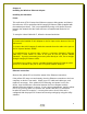
Above: (left) schematic of Virtual Cable Wi-Fi Access Point connected to a network.
(right) schematic of Virtual Cable Wi-Fi Station connected to a terminal PC.
Ethernet Connection (station)
When configured as a Station, the Virtual Cable Wi-Fi can be connected to a
computer’s Ethernet port, or a router's WAN port via the included Straight-
through UTP cable. Please note that, as dictated by the 802.11 standards, only
one MAC address can be supported by a Station radio. As a result, a Virtual
Cable Wi-Fi configured as a Station will not function properly when
connected to a hub or switch plugged in with multiple computers/network-
devices. So as a rule, straight-through cable is always used to connect a Virtual
Cable Wi-Fi Station to a computer or a network device.
If you wish to connect multiple PCs via a single Virtual Cable WiFi station, see
"Appendix C: Virtual Cable Wi-Fi Applications"
Status LEDs
Use the LED status indicators to make sure that the Virtual Cable Wi-Fi station is
communicating properly:
LED Color Light Blinking Pattern
ON RED Steady on
RX GREEN Steady on
TX RED on, when transmitting RF signal
LINK YELLOW Flickering when communicating over the Ethernet
port; steady-on when Ethernet connection is absent