
User's Manual


5
1. Introduction
2411EZYLINK-E is a point-to-multiple-points wireless data networking system. It can be used by internet
service providers as a means of last-mile connection to the users. It can also be used to form a campus
network. Its data-transmitting burst rate is 11 Mbps.
1.1 Theory of Operation
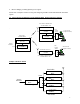
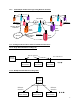
The 2411EZYLINK-E consists of the Base Station 2411EZYLINK-E-BST and the Client Station
2411EZYLINK-E-CPE. The Base Station consists of the Access Management Unit (AMU) 2411EZYLINK-
E-BST-AMU and the Base Radio Transceiver 2411EZYLINK-E-BST-TRX. The base station is installed at
the site that has access to the Internet backbone or at the central site of a campus network. The Client
Station consists of the Client Radio Transceiver 2411EZYLINK-E-CPE-TRX and/or the Buffer Box
2411EZYLINK-E-CPE-BFB. The client station is installed at the Internet service subscribers’ site or the
satellite site in a campus network.
All the 2411EZYLINK-E equipment is designed to work with Ethernet interface. The Radio Transceiver
converts the Ethernet data packets into radio packets and uses direct sequence spread spectrum
modulation to turn the data packets into 2.4 GHz radio signals.
The Base Radio Transceiver and the Client Radio Transceivers each has a unique RFID. A packet to be
relayed between two stations uses the RFID of the originating transceiver as its source address and the
RFID of the intended receiving transceiver as its destination address. The packet transmitted by the
originating transceiver can be received by all the transceivers within the effective receiving range. Only
the transceiver with the correct RFID matching the destination address will process the information
contained in the packet. All the other stations will discard the packet.
Each packet is encrypted before being transmitted by the radio. The RF channel and the encryption code
have to be set the same for two stations to communicate with each other. The Base Station and all the
Client Stations are pre-configured in the factory with the same default RF channel and encryption code.
The user system administrator can use OTC’s system administration software to change the settings (see
Chapter 4 for details).
The communication between the Client Stations and the Base Station is based on a polling process. The
RFID of each Client Station to be served by a Base Station needs to be registered in a polling list stored in
the Base Station transceiver. The OTC’s system administration software can be used to add or delete the
RFIDs of the Client Station transceivers in the Base Station transceiver.
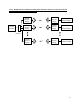
In addition to the Client Station access management, The Access Management Unit (AMU) provides the
following functions:
1. Flow control between the network backbone and multiple Base Radio Transceivers.
2. SNMP and Web based Interface for monitoring and configuring the multiple Base RadioTransceivers
(one AMU can be connected to up to 4 Base Radio Transceivers via a switching hub) and the Client
RadioTransceivers servered by each Base Transceiver Radio.
3. Ethernet bridging, including Spanning Tree support.
The use of the Buffer Box at the Client Station is optional. If the client site has only a small number of
computer stations, the use of the Buffer Box may not be required. When the number of computer stations
on the client site is greater than eight, it is recommended that a Buffer Box be used with the Client Radio
Transceiver.
The Buffer Box provides the following functions:
1. Flow control between the client’s local network and the Client Transceiver Radio.