TECHNICAL MANUAL For WiSER2400.IP WiSER2400.Plus 802.11 Wireless Serial Solutions http://www.otcwireless.
Technical Manual For WiSER2400.IP WiSER2400.Plus 802.11 Wireless Serial Solutions Copyright Information in this document is subject to change without notice. Complying with all applicable copyright laws is the responsibility of the user. No part of this document may be reproduced or transmitted in any form or by any means, electronic or mechanical, for any purpose, without the express written permission of the seller.
TABLE OF CONTENTS INTRODUCTION 4 1. Installation 6 1.2 Installation of WiSER2400 Administrative Software 9 1.3 Installation of VirCOM, the virtual serial COM port redirector 9 2. WiSER Deployment Strategies 10 2.1 Using the WiSER2400 in a Point-to-point Link 10 2.2 Using the WiSER2400 in a Point-to-multiple point Link 14 Using the WiSER 2400 Administration Software 18 3.1 Overview 18 3.2 Password Protection 20 3.3 Link Status 21 3.4 Configuration Page 22 3.
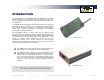
INTRODUCTION The WiSER2400.IP and the WiSER2400.Plus are IEEE 802.11b compliant devices with built-in serial interfaces. They are designed to allow nonwirelessly enabled serial devices to be connected and fully integrated into an 802.11 Network. The WiSER2400 receives data from equipment with serial ports; converts the serial data into 802.11 compliant TCP or UDP data packets and transmits these packets wirelessly.
Key Features Specifications Works with any 802.11b or 802.11g access point Model WiSER2400.IP; WiSER2400.Plus Supports peer-to-peer networking with one another or any 802.11b/g Standard 802.11 and 802.11b station devices Host Interface Supports TCP/IP and UDP networking over 802.11 Frequency RS232 (WiSER2400.IP) RS232/485/422 (WiSER2400.Plus) 2.4GHz – 2.
1. Installation 1.1.1 Standard Hardware WiSER2400.IP 1 WiSER2400.IP radio 1 RS232-P cable 1 RS232-C cable 1 ac-dc power adapter 1 pair of Velcro mounting pads 1.1.2 Power WiSER2400.IP Uses 5V DC for input power. adapter is provided. 1.1.3 Serial Connections An AC-to-DC power The RS-232-P cable is for connecting the WiSER2400.IP to the RS232 port of DCE equipment (whiteboard, instrument, etc.) during communication. It terminates in a male DB-9 connector and is labeled “Board” on the cable.
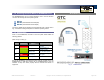
1.1.4 Selecting the Serial Mode for WiSER2400.Plus WiSER2400.IP The WiSER2400.Plus has a 4-position dipswitch next to the mini Phoenix connector for selecting the serial operating mode: RS-232 RS-485 (select RS-485 and half-duplex) RS-422 (select RS-485 and full-duplex) The factory default has the dipswitch set in the RS-232 mode. Please refer to Fig. 4 for details in setting the dipswitch for different operating modes. 1.1.
WiSER2400.Plus This section describes the signals expected on the mini-Phoenix connector pins. 10-pin mini-Phoenix terminal: Dip Switch: Pin: 1. 2. 3. 4. 5. 6. 7. 8. 9. 10. Location (from left to right) DATA+(RS-485) DATA- (RS-485) N/C TX+ (RS-422) TX- (RS-422) RX+ (RS-422) RX- (RS-422) N/C V+ (Up to +32 VDC) GROUND DB 9 male connector: Pin: 1. 2. 3. 4. 5. 6. 7. 8. 9. 1. #RS232/485 selector 2. #Full/Half duplex selector 3. 120 ohm termination -- 422 RX pair 4.
1.2 Installation of WiSER2400 Administrative Software 1.3 Installation of VirCOM, the virtual serial COM port redirector 1.2.1 System Requirements 1.3.
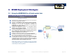
2. WiSER Deployment Strategies 2.1 Using the WiSER2400 in a Point-to-point Link 2.1.1 Using the WiSER2400 in a point-to-point link Scheme 1 See Figure 5 (overleaf) Connect the PC to an 802.11b/g access point, or use a PC with a built-in 802.11b/g wireless LAN card. Configure the WiSER2400 to match its serial parameters (baud rate, parity bit, … etc.) with that of the serial device it is to be attached to.
Fig. 5 WiSER 2400 Technical Manual Version 2.16 Copyright 2001-2005, OTC Wireless, Inc.
2.1.2 Using the WiSER2400 in a point-to-point link Scheme 2 See Figure 6 (overleaf) Configure the WiSER2400 on the device side to match its serial parameters (baud rate, parity bit, … etc.) with that of the serial device it is to be attached to. Configuration can be done by temporarily connecting the WiSER2400, by a serial cable or wirelessly, to a PC running the WiSER2400 administration software.
Fig. 6 WiSER 2400 Technical Manual Version 2.16 Copyright 2001-2005, OTC Wireless, Inc.
2.2 Using the WiSER2400 in a Point-to-multiple point Link 2.2.1 Using the WiSER2400 in a point-to-multiple point link Scheme 3 See Figure 7 (overleaf) Connect the PC to an 802.11b/g access point, or use a PC with a built-in 802.11b/g wireless LAN card. Configure each WiSER2400 to match its serial parameters (baud rate, parity bit, … etc.) with that of the serial device it is to be attached to.
Fig. 7 WiSER 2400 Technical Manual Version 2.16 Copyright 2001-2005, OTC Wireless, Inc.
2.2.2 Using the WiSER2400 in a point-to-multiple point link Scheme 4 See Figure 8 (overleaf) Configure each WiSER2400 on the device side to match its serial parameters (baud rate, parity bit, … etc.) with that of the serial device it is to be attached to. Configuration can be done by temporarily connecting the WiSER2400, by a serial cable or wirelessly, to a PC running the WiSER2400 administration software.
Fig. 8 WiSER 2400 Technical Manual Version 2.16 Copyright 2001-2005, OTC Wireless, Inc.
3. Using the WiSER 2400 Administration Software 3.1 Overview This chapter describes the functionality and operations of the WiSER2400 Diagnostic and Configuration administrative software program. The WiSER2400 administrative program is supported on Microsoft Windows® 98(SE), NT, Millennium, 2000, and XP. To use the administrative program to monitor and configure the WiSER2400, the PC can be connected to the WiSER2400 either directly through the serial port by cable or via a wireless network connection.
Fig. 10 Administrative software dialog with a PC connected to the WiSER2400 via a serial cable Fig. 11 Administrative software dialog with a PC connected to the WiSER2400 wirelessly. Fig. 10 shows the administrative program interface when the PC is connected with the WiSER2400 through the serial port by a cable. The user first needs to select the proper COM port on the PC and its baud rate, byte size, and parity (as shown in the top of Fig.
3.2 Password Protection Before any change/modification can be made to the configuration of a WiSER2400, a password must be submitted before the configuration command is executed. After entering the password, click “OK” to proceed “Cancel” to stop. The Password Utility is also used to add or change a password for a WiSER2400 unit. Fig. 12 WiSER2400 Password Utility panel NOTE: The default password of WiSER2400 is none. (Leave the field blank). WiSER 2400 Technical Manual Version 2.
3.3 Link Status The Link Status page displays wireless link information such as SSID (of the access point the WiSER2400 is connected with, or the group ID in an ad-hoc peer-to-peer network), the firmware version and release date, role of the radio, RF channel, port status, link quality, and signal strength. Use the Refresh button to retrieve/update the Link Status information. Fig. 13 WiSER2400 administration software Link Status panel WiSER 2400 Technical Manual Version 2.
3.4 Configuration Page The Configuration page has four sections: Serial Port Serial IP Proxy Wireless Port Peer Host After selecting the desired section, click on the Refresh button at the bottom of the page to bring up the current settings. After changing the settings, use the Apply button to save the new settings to the WiSER2400. Fig. 14 WiSER2400 administration software Configuration/Serial Port panel WiSER 2400 Technical Manual Version 2.16 Copyright 2001-2005, OTC Wireless, Inc.
End Frame Byte: 3.4.1 Serial Port (Refer to Fig. 14 on previous page). Serial Parameter Baud rate: This value specifies the character that signals the end of a data-string, and the data would be sent to the destination unit right after the radio receives the designated character. Range 0x00 to 0x1F. Default value: 0x0D = Carriage Return for setting the baud rate of the WiSER2400’s serial port. Supported values: 1200, 2400, 4800, 9600, 14400, 19200, 38400, 57600, and 115200 bps.
3.4.2 Serial-IP-Proxy MAC Address: the MAC address of the WiSER2400. This field is not modifiable. DHCP Enable: Allows the WiSER2400 to obtain IP address from a DHCP server. IP Address: The IP address of the WiSER2400, user configurable. Listen Port: The port number used by the WiSER2400 to communicate. This is the source port number in the TCP/UDP packets sent from this WiSER2400. Default value: 8002. Subnet Mask: For configuring the subnet mask settings.
3.4.3 Wireless Port Wireless Settings The SSID of the access point the WiSER2400 is to be associated with; or the peer-to-peer group ID when the WiSER2400 is operated in the adhoc mode. Maximum: 32 characters. A blank entry is allowed. When left blank, the WiSER2400 would interpret it as ‘ANY’ and will try to join any available open wireless network. SSID: Network Type: Infrastructure mode: for the WiSER2400 to be connected to an access point.
3.4.4 Peer Host Destination Unit MAC Address: The MAC address of the destination device. IP Address: The destination IP address of the device that the WiSER2400 radio is set to communicate with. For TCP server and UDP modes, the IP Address can be left as 0.0.0.0. In TCP client mode, a valid IP address is required. Listen Port: The port number the destination device listens on to receive the TCP/UDP packets.
The remaining fields in the Encryption page are described below. 3.5 Encryption The WiSER2400 supports Wired Equivalent Privacy (WEP) security for both 64-bit and 128-bit encryptions. The Encryption page contains two sections: 3.5.1 Encryption This section allows the user to choose from three encryption options: 64 bits, 128 bits or none (disabled). The WiSER2400 uses the shared key scheme when either 64 or 128-bit key is selected.
3.6.2 WLAN Statistics: 3.6 Statistics The statistics of the data traffic through both the serial (COM) port and the wireless link is displayed in this page. Use the Refresh button located at the bottom of the page to retrieve/update the most current statistics. 3.6.1 RS232 Statistics: COM Sent: The total number of bytes sent by the WiSER2400 through the serial (COM) port.
3.7 Admin Under this tab users will find tools for Administrative settings: Change Password: Used for changing the password. Please keep a safe record of changed passwords as losing the password could prohibit future changes to the unit’s configuration. Set Factory Default: This function resets all of the WiSER2400’s settings back to its factory defaults.
APPENDIX Troubleshooting Blank Pages Appear When Opening the Administrative Program Poor Link Quality This is possibly due to the unavailability of the COM port. Check the Connection and Status fields at the bottom of the program’s main window. Press the Connect button again to see if the status indicates “Connected.” If not, check to see if you have another program running that accesses (or protects) the same COM port.
Recovering from the Data Only Mode Limited Warranty There are two approaches for recovering the WiSER2400 radio from the Data Only Mode. First is to use the Administrative software under wireless connection since the WiSER2400 radio will still take configuration command from the wireless port even when it is running Data Only Mode. Use the alternative approach if the WiSER2400 can only be linked through a serial connection. The instruction for the alternative approach is given below. 1. 2. 3. 4. 5.
Regulatory Compliance FCC Part 15 Declaration of Conformity (DoC) FCC Radiation Exposure Statement The equipment is confirmed to comply with the requirements of FCC Part 15 rules. The operation is subject to the following two conditions: This equipment complies with FCC radiation exposure limits set forth for an uncontrolled environment. This equipment should be installed and operated with minimum distance of 20cm between the radiator & your body.