
User's Manual

ACR-201-G Technical Manual
3
Chapter 2 Installation
Safety Statements
Use only the power supply adaptor provided with this product or the
manufacturer's authorized replacement power supply. Connect the power cord to
a properly grounded electrical outlet that is near the product and easily
accessible.
Refer service or rep airs, other than those described in the user
documentation, to a professional service person.
DANGER: Do not set up this product or make electrical connections during
a lightning storm
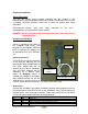
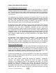
Installing the Hardware
Power
Power is supplied to the radio via
the supplied USB power cord
plugged into a compliant USB-host
port. An optional DC adapter can
be purchased from OTC Wireless,
Inc.
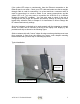
Ethernet Connection
The ACR-201-G is to be connected
to any device’s Ethernet port via
the included white straight-through
UTP cable. Please note that, as
dictated by the 802.11 standards,
only one MAC address can be
supported by a Station radio,
unless IP Bridging feature is
enabled (see Chapter 3 for details),
then multiple devices can use the
ACR-201-G for access via a hub or
a switch, where the blue crossover UTP cable needs to be used.
Status LED’s
Connect the 100-BaseT port (which resembles an over-sized telephone jack) on
the bottom panel of the ACR-201-G to the 100-BaseT port of the computer (or
network device, such as a hub or switch). Power on the ACR-201-G, the LED’s
on the front panel should exhibit the following patterns:
LED Color Light Pattern
ON Red Steady ON
RX Green Steady ON
TX Red Blinking ON, when transmitting 802.11 signal
LINK Yellow Blinking ON, when communicating over the Ethernet port
Cat5 Straight Through
5V USB Power
Adaptor
ACR-201