
Instruction Manual


I nstallation
Instructions
For models: OTH700S (240GA) /
OTH702S (120GA) / OTH800D (240D)
Material
! One (1) power base
" Two (2) screws
# Four (4) solderless connectors for copper wires
NOTE: Special CO/ALR solderless connectors must be used when
connecting with aluminum conductors.
$ One (1) floor sensor and one (1) flat tip screwdriver (OTH700
series only)
Installation Guidelines
Turn off power to the heating system at the main power panel
to avoid electrical shock. Installation should be carried out by
an electrician.
High voltage thermostats must be installed onto an electrical
box.
For a new installation, choose a location about 5 ft. above the
floor.
The thermostat must be installed facing the heating system
(except for floor heating installations) and on an inside wall.
Avoid locations where there are air drafts (top of staircase, air
outlet), dead air spots (behind a door), direct sunlight, con-
cealed chimneys or pipes or an air diffuser.
OUELLET CANADA INC. ONE (1) YEAR LIMITED WARRANTY
OUELLET CANADA INC. warrants the component parts of the OTH700/OTH800
series against defects in material and workmanship for a one (1) year period from the
date of purchase, under normal use and service, when proof of purchase of such is
provided to the manufacturer.
The obligation of Ouellet Canada inc., under the terms of this warranty, will be to supply
a new unit and this releases the manufacturer from paying the installation costs or
other secondary charges linked to replacing the unit or the component part(s).
180, 3rd Avenue
P.O. Box 188,
L’ISLET, Quebec, Canada G0R 2C0
If you have any questions concerning the installation of this
power base, call our technical support team at:
Tel.: Quebec area: (418) 247-3947
Canada / U.S.: 1-800-463-7043
Fax: (418) 247-7801
Sales: vente@ouellet.com
Web: www.ouellet.com
Monday to Friday from 8:00 AM to 5:00 PM EST.
Tech nical Specifications
Storage: -4°F to 120°F (-20°C to 50°C)
GFCI: GA = 5 mA, GB = 30 mA trip level
Econo input: requires a dry contact
Size (H•W•D): 124 x 70 x 23 mm (4.89 x 2.76 x 0.91 in)
Certifications:
Model Supply Max. Load Power
Conn.
a
a. Connection type: 4w = 4 wires, DP = Double Pole, SP = Single Pole
GFCI
OTH702S (120GA) 120 VAC, 50/60Hz 15 A 1800 W 4w/DP 5 mA
120GB 120 VAC, 50/60Hz 15 A 1800 W 4w/DP 30 mA
120S 120 VAC, 50/60Hz 20 A 2400 W 4w/SP
OTH700S (240GA)
240 VAC, 50/60Hz
208 VAC, 50/60Hz
15 A
3600 W
3120 W
4w/DP 5 mA
240GB
240 VAC, 50/60Hz
208 VAC, 50/60Hz
15 A
3600 W
3120 W
4w/DP 30 mA
240S
240 VAC, 50/60Hz
208 VAC, 50/60Hz
20 A
4800 W
4160 W
4w/SP
OTH800D (240D)
240 VAC, 50/60Hz
208 VAC, 50/60Hz
15 A
3600 W
3120 W
4w/DP
277S 277 VAC, 50/60Hz 15 A 4155 W 4w/SP
347S 347 VAC, 50/60Hz 15 A 5200 W 4w/SP
In tro d uc ti o n
This power base is designed to power an OTH700/800 Series
control module.
Refer to the technical specifications for maximum resistive load.
R
CUS
R
CUS
18/05/2004 400-609-000-B
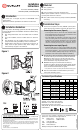
Fi g ure 1
Fi g ure 2
Installation Steps
! Connect the rear power base wires (FIGURE 1) to the power
and to the load using solderless connectors for copper wires.
Connecting the floor sensor (Figure 2)
• Insert the probe into one of the two holes available below
the terminal board and connect the wires to terminals 3 and
4 (no polarity needs to be respected).
• The cable follow the wall down to the floor and must not
cross any heating wires nor be directly on or adjacent to a
heating wire. For maximum performance, the sensor probe
should be centered between the wires in the mat. Run the
sensor in a raceway for easy access to a defective sensor.
Connecting the econo input (Figure 2)
• Insert the cable (use an 18 to 22 gauge flexible wirecable)
into one of the two holes available below the terminal board
and connect terminals 1 and 2 of the base to terminals 1
and 2 of the CT240’s auxiliary output or any of the dry con-
tact outputs of the CT241 (Aube telephone controllers).
" Push the excess wire (except for the probe/econo) back into
the electrical box to prevent interference with the thermostat.
Warning: the cable must run on the left side of the cavity
located on top of the terminal board. Secure the power base
to the electrical box using the provided screws.
# BEFORE mounting the control module onto the base,
configure the switches located on the control module (heating
cycles * and display) and install the control module onto the
base (refer to the control module user guide).
*
this power base must be used only with 15-minute heating cycles.
$ Once the control module is installed onto the power base,
return power to heating system.