AXS Port SunSpec Modbus Interface Owner’s Manual
About OutBack Power Technologies OutBack Power Technologies is a leader in advanced energy conversion technology. Our products include true sine wave inverter/chargers, maximum power point tracking charge controllers, and system communication components, as well as circuit breakers, batteries, accessories, and assembled systems. Contact Information Telephone: +1.360.435.6030 +1.360.618.4363 (Technical Support) +1.360.435.
Table of Contents Introduction.................................................................................................3 Welcome to OutBack Power Systems ...........................................................................................................................3 Audience .................................................................................................................................................................................3 AXS Port Features....................
Table of Contents List of Figures Figure 1 Figure 2 Figure 3 Figure 4 Figure 5 Figure 6 Figure 7 Figure 8 Figure 9 2 Features ................................................................................................................................................ 3 Wall Mount .......................................................................................................................................... 3 DIN Rail Mount .....................................................................
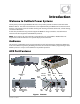
Introduction Welcome to OutBack Power Systems Thank you for purchasing the OutBack AXS Port. This product provides communication with other OutBack devices. The device uses Ethernet access implemented by the Modbus Transmission Control Protocol. The SunSpec protocol enables sending and receiving of remote commands, control settings, and status information. At this time, the AXS Port only provides support for OutBack charge controllers. Future firmware revisions will allow support for other OutBack products.
Introduction Accessories ¾ The AXS Port can use a Type 2 microSD card for logging operational status information about the system. A 2 GB microSD card is included. The SD card is also required for performing firmware updates. ¾ The AXS Port can be equipped with a clip for mounting on a DIN rail. This clip is included. ¾ The AXS Port can be equipped with an additional temperature sensor to supplement the battery sensor used by other OutBack devices. Ambient temperature of a room, PV array, etc.
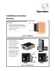
Operation Installation Instructions Mounting To mount the AXS Port directly on a wall or flat surface: 1. Insert two screws (appropriate for the surface) into the mounting holes at the top and bottom of the device. The holes will accept up to a #6 screw. 2. Tighten securely. Figure 2 Wall Mount To mount the AXS Port on a DIN rail: 1. Orient the AXS Port upright so that the DIN rail clip is next to the rail. 2. Next, place the clip against the DIN rail. Hook the upper edge of the clip over the DIN rail. 3.
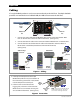
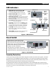
Operation Cabling If a single OutBack product is used, it can connect directly to the AXS Port. If multiple OutBack products are networked on an OutBack HUB, the HUB can connect to the AXS Port. - OutBack Device Cable Network Cable HUB/Device Port Network Port 1. Connect the CAT5 cable from the OutBack device to the connection labeled “HUB Port” on the AXS Port. The Power LED will illuminate. (See Figure 6.) 2. Connect the network cable to the connection labeled “Network Port” on the AXS Port. 3.
Operation LED Indicators ¾ OutBack Device Communications LED: Blinks when data is being transmitted or received from OutBack devices on this port. HUB/Device Port Modbus Activity LED (green) ¾ Modbus Activity LED: Blinks when Modbus registers are being written or read. ¾ Ethernet Activity LED: Illuminates when the AXS Port is transmitting or receiving Ethernet packets. ¾ Ethernet Link LED: Illuminates when the AXS Port has established an Ethernet link with a network, or with the Internet.
Operation SunSpec Blocks The AXS Port uses the SunSpec protocol to assemble blocks of data on each connected product. The SunSpec client software can read or write to each field in a data block on the AXS Port. The fields are used for remote commands, control settings, or status information on the OutBack product. A user with SunSpec client software can use the following tables to interpret these blocks. Samples of the SunSpec client software are available at www.outbackpower.com.
Operation Table 1 OutBack Block Start End Size R/W Field Name OutBack_Minor_Firmware _Number 4 4 1 R Type Units Scale Factor Contents uint16 N/A N/A Read Only 5 6 13 5 12 20 1 7 8 R R W uint16 N/A String (14) N/A String (16) N/A N/A N/A N/A 21 22 21 23 1 2 24 25 2 26 27 2 28 29 2 30 32 31 32 2 1 33 52 20 53 68 16 69 69 1 70 77 8 78 97 20 98 98 1 99 99 1 100 124 25 125 144 20 145 164 20 165 165 1 166 190 25 191 210 20 211 231 239 230 238
Operation Charge Controller Block: This block is usable for most OutBack charge controllers with the exception of the OutBack MX60. It is a status-only block and does not contain command or control fields.
Operation Table 3 Start End Size R/W Name CCconfig_Absorb_Time_ 11 11 1 R/W Hours CCconfig_Absorb_End_ 12 12 1 R/W Amps 13 13 1 14 14 15 Charge Controller Configuration Block Type Units uint16 Hours uint16 Amps R/W CCconfig_Rebulk_Volts uint16 Volts 1 R/W CCconfig_Float_Volts uint16 Volts 15 1 R/W CCconfig_Bulk_Current uint16 Amps 16 17 18 16 17 18 1 1 1 R/W CCconfig_EQ_Volts R/W CCconfig_EQ_Time_Hours R/W CCconfig_Auto_EQ_Days uint16 uint16 uint16 Volts Hours Days 19 19 1 R
Operation Table 3 Start End Size R/W Name CCconfig_AUX_Divert_ 48 48 1 R/W Relative_Volts CCconfig_AUX_Divert_ 49 49 1 R/W Hyst_Volts CCconfig_Major_Firmware 50 50 1 R _Number CCconfig_Mid_Firmware_ Number 51 51 1 R CCconfig_Minor_Firmware _Number 52 52 1 R CCconfig_Set_Data_Log_ Day_Offset 53 53 1 W CCconfig_Get_Current_ Data_Log_Day_Offset 54 54 1 R CCconfig_Data_Log_Daily_ 55 55 1 R AH CCconfig_Data_Log_Daily_ kWH 56 56 1 R CCconfig_Data_Log_Daily_ Max_Output_Amps 57 57 1 R CCconfig_Data_Log_Daily_ Max_O
Operation Misc Warning mode Ac mode Battery voltage Error mode Sell current Operating mode Buy current Ac input voltage Ac output voltage Invrt current Chrg current Device type Port Date Time NOTE: This header line is NOT included in the download.
Operation To update the firmware using an FTP site and the SD Card: 1. Connect to the AXS Port using the FTP site. 2. Copy the update file from the OutBack website to the UPDATEFW directory on the microSD card. NOTE: It may be necessary to create this directory on the SD card first, using the FTP client. 3. Once the update file is copied, disconnect the FTP client from the AXS Port. 4.
Troubleshooting Basic Troubleshooting Table 5 Basic Troubleshooting Symptom Possible Cause Remedy Power LED does not illuminate The OutBack device may not be powered; the CAT5 cable may be damaged or disconnected Make sure the OutBack device is powered; check the cable connection or replace the cable Ethernet Link LED does not illuminate The CAT5 cable may not be making Check the cable connection or replace the cable; connection; network port may be use another network port; verify that the inactiv
Troubleshooting THIS PAGE INTENTIONALLY LEFT BLANK.
Specifications Regulatory Specifications Table 7 Regulatory Specifications Specification Details FCC Compliance CE Compliance RoHS Compliance Part 15, subpart B Yes Yes Device Specifications Table 8 Device Specifications Specification Details Power Status Indicators Clock Supplied by OutBack device Seven LED indicators On-board real-time clock with battery backup TCPIP, DNS, SMTP, FTP, DHCP, NTP Hub/Device Communications Temperature Sensor Modbus TCP to the SunSpec standard OutBack Proprietary 10
North America: 5917 – 195th St NE Arlington, WA 98223 USA +1.360.435.