
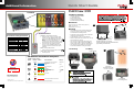
OutBack Power FLEXmax 100 Quick Start Guide
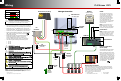

Wiring
900-0204-01-00 REV D
©2017 OutBack Power Technologies. All Rights Reserved.
FLEXmax 100
o Tighten all wire lugs and ground terminals to 4 Nm (35 in-lb) torque.
o Use copper wiring only (rated 90°C or higher). Refer to the NEC and
other electrical codes for PV array cable sizing, length, and ampacity.
o Use #4 AWG (25 mm
2
) wire (minimum) for the controller output
terminals to the batteries. They can accept up to #2 AWG (35 mm
2
).
o Use #6 AWG (16 mm
2
) wire (maximum) for the ground terminals.
o Negative-ground installation is depicted here. (The bond is shown
in D.) Positive grounding is also permitted, but special
arrangements are required.
o External disconnect and overcurrent protective devices must
be sized and provided by the installer. For input circuit
breakers, OutBack offers 40 Adc to 80 Adc devices. For
the output, OutBack offers either 100 Adc or 125 Adc devices.
o This product supports the following nominal battery systems:
24 volts
36 volts
48 volts
Negative
Positive
Ground
DC LEGEND
Battery Sense Terminals
These terminals (C) monitor battery voltage more accurately than the main
cables. (If not connected, the controller will revert to using its own readings,
which may not be as accurate.) A twisted-pair cable is recommended. The
connections are made directly on the battery terminals.
A fuse or other protection must be applied to the
sense conductors. Recommended protection is:
o Fast-acting device
o Cold resistance 10 ohms or less
o 80 Vdc or greater
o 1 Adc or smaller
Ports
The active ports are the RTS port
and the HUB port. The HUB port is
used to network the controller to a
HUB Communications Manager
product or one of several OutBack
system display products as shown
here. (See the FLEXmax 100
Owner’s Manual for more information.)
See below for more information on
the RTS function.
NOTE: The ports shown here as
D
EVICE and LAN are not currently
active. These ports can be activated
in the future using firmware updates.
MATE3s
System Display
and Controller
LED Indicators
(see back page)
Charge Controller
PV
Combiner
Photovoltaic (PV) Array
Ground
Bus
Battery
Disconnect
(external)
Negative
Bus
PV
Disconnect
(external)
ON
OFF
ON
OFF
B
C
C
B
A
Ground
Electrode
Conductor
RTS
HUB Port
PV– BAT+
PV+
Bonding
Jumper
(negative-
ground)
D
The RTS (B) attaches to the batteries
near the center of the battery bank.
Battery performance will change when
not at room temperature (77°F or 25°C).
Batteries may be undercharged if cold
or overcharged if hot. When the RTS is
installed, the FLEXmax 100 adjusts the
charging voltages to avoid this problem.
This compensation affects the Absorb
and Float set points. Equalization is
not compensated.
Remote Temperature
Sensor (RTS)
NOTE: See the FLEXmax 100 Owner’s Manual for more notes on all
topics above. This also includes installation of rapid shutdown devices,
multiple controllers, and ground fault operation (GFDI).
Equalize
Button
MicroSD Card
The rapid shutdown terminals are left disconnected at the factory.
The FLEXmax 100 will not power up until terminals 1 and 3 in C are
connected together. See the back page for more information.
Line
Load
Line
Load
Reset Button
NOTE: This button is used to update
firmware and other functions. It does
not reset the controller to the factory
default settings. (See the Owner’s
Manual for information on both topics.)