
OutBack Power FLEXpower ONE FXR Series Quick Start Guide
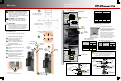

> 90% (blinks if charge parameters are met)
Color
Red
Yellow
Yellow
Yellow
Green
≥ 80%
≥ 70%
≥ 60%
≥ 60% off, < 60% solid, < 50% blinks
Battery State-of-Charge
FN-DC LED Indicators
Quick Start Guide
Contact Technical Support:
Telephone: +1.360.618.4363
Email: Support@outbackpower.com
Website: www.outbackpower.com
Phase
Active Error
DC
AC IN
AC OUT
RedYellow
Yellow
Yellow
Red
Red
Surge Protector LEDs
LED Indicators on the Inverter
Inverter Status LED Indicators
Green
Yellow
Red
Inverter on (solid) or standing by (flash)
AC source in use (solid) or standing by (flash)
Inverter error or warning (see manual)
Green
Yellow
Red
12.5 Vdc or higher
11.5 to 12.4 Vdc
11.4 Vdc or lower
Color
Battery Status LED Indicators
25.0 Vdc or higher
23.0 to 24.8 Vdc
22.8 Vdc or lower
50.0 Vdc or higher
46.0 to 49.6 Vdc
45.6 Vdc or lower
12 V Inverter 24 V Inverter 48 V Inverter
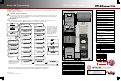
Inverter/Charger
AC Conduit Box (with Bypass Assembly)
DC Conduit Box (with Inverter Disconnect
System Display and Controller
PV Charge Controller
Communications Manager
Main Electrical Panel
(or overcurrent device for AC source)
Electrical Distribution Subpanel
(Load Panel)
Battery Bank
FLEXnet DC Monitor (FN-DC)
Customer-Supplied Components
FLEXpower System Products
Major Components
Photovoltaic (PV) Array
(with PV Combiner Box)
AC Source
Utility Grid, or
AC Generator
Remote Temperature Sensor (RTS)
Surge Protector
IMPORTANT:
Not intended for use with
life support equipment.
Supports the OPTICS RE™ online tool for a cloud-based remote monitoring and control application.
Please refer to the OPTICS RE setup instructions, or visit www.outbackpower.com to download.
The firmware revision of all
devices can be confirmed by
navigating from the MATE3
Main Menu as shown below.
Upgrades to the firmware
revision can be downloaded
from the OutBack website
www.outbackpower.com.
Firmware Revision
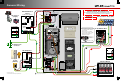
Configuration Wizard
The MATE3 Configuration Wizard allows quick setup of parameters that apply to all systems. The Configuration Wizard is reached from
the MATE3 Main Menu as shown below.
900-0132-01-01 REV A.vsd
©2013 OutBack Power Technologies. All Rights Reserved.
Setup and Programming
!
CAUTION: Equipment Damage
These procedures should be done by a qualified installer who is trained on programming inverter power systems. Failure to set
accurate parameters for the system could potentially cause equipment damage. Damage caused by inaccurate programming is
not covered by the limited warranty for the system.
IMPORTANT
Check the firmware revision of all OutBack devices before use. The MATE3 system display must be revision 003.002.xxx or
higher. If the revision is lower, the MATE3 and inverter may not communicate or operate correctly.
Note: See the MATE3
manual for details on
generator control.
Off Grid
Grid Tied Backup
The Continue key advances between shunt screens as appropriate.
After the last shunt screen, it advances the display to the Setup Complete screen.
The Continue key advances the display
to the Shunt screens if the FLEXnet
DC is installed. If the FLEXnet DC
is not installed, the display advances to
the Setup Complete screen.
Configuration Wizard
New Configuration >>
Existing Configuration >>
Restore Configuration >>
Wizard System Type
System Type Grid Tied
System Voltage 48 VDC
Array Wattage 1000
Battery Type FLA Capacity 500 Ah
Back Continue
Wizard Battery Charging
Absorb Voltage 57.6 VDC Time 1.0
Float Voltage 54.4 VDC Time 1.0
Equalize Voltage 60.0 VDC Time 3.0
Re-Float Voltage 44.0 VDC
Back Continue
Configuration Wizard
New Configuration Initialized
Back Continue
Wizard Grid Use Schedule
Period 1 Enable N
Weekday Use 0:00 Drop 0:00
Weekend Use 0:00 Drop 0:00
Back Continue
Wizard Grid Use Schedule
Period 2 Enable N
Weekday Use 0:00 Drop 0:00
Back Continue
Wizard Grid Use Schedule
Period 3 Enable N
Weekday Use 0:00 Drop 0:00
Back Continue
Wizard Battery Monitor
Shunt B
Connection Charge Controller
Back Continue
Wizard Grid Use Schedule
Period 3 Enable N
Weekday Use 0:00 Drop 0:00
Back Continue
Wizard Grid Use Schedule
Period 1 Enable N
Weekday Use 0:00 Drop 0:00
Weekend Use 0:00 Drop 0:00
Back Continue
Wizard Generator Configuration
Generator Installed N
Generator Type AC Size 5.0 kW
Generator Start Manual
AUX Output Device Port 1
Back Continue
Wizard AC Configuration
AC Output Voltage 120 VAC
AC Phase Single
AC Input Breaker Size 50 A
Maximum Output Load 33 A
Back Continue
Wizard Grid Use Schedule
Period 2 Enable N
Weekday Use 0:00 Drop 0:00
Back Continue
Wizard Generator Configuration
Generator Installed N
Generator Type AC Size 5.0 kW
Generator Start Manual
AUX Output Device Port 1
Back Continue
Wizard Battery Charging
Absorb Voltage 57.6 VDC Time 1.0
Float Voltage 54.4 VDC Time 1.0
Equalize Voltage 60.0 VDC Time 3.0
Re-Float Voltage 44.0 VDC
Back Continue
Wizard AC Configuration
AC Output Voltage 120 VAC
AC Phase Single
AC Input Breaker Size 50 A
Maximum Output Load 33 A
Back Continue
Wizard System Type
System Type Backup
System Voltage 48 VDC
Array Wattage 1000
Battery Type FLA Capacity 500 Ah
Back Continue
Wizard Battery Monitor
Shunt A
Connection Inverter
Back Continue
Wizard AC Configuration
AC Output Voltage 120 VAC
AC Phase Single
AC Input Breaker Size 50 A
Maximum Output Load 33 A
Back Continue
Wizard Battery Charging
Absorb Voltage 57.6 VDC Time 1.0
Float Voltage 54.4 VDC Time 1.0
Equalize Voltage 60.0 VDC Time 3.0
Re-Float Voltage 44.0 VDC
Back Continue
Wizard System Type
System Type Off Grid
System Voltage 48 VDC
Array Wattage 1000
Battery Type FLA Capacity 500 Ah
Back Continue
Main Menu
Settings >>
Configuration Wizard >>
Device Data Logs >>
Event Logs >>
Firmware Update >>
Configuration Wizard
New Configuration
Wizard Generator Configuration
Generator Installed Y
Generator Type AC Size 5.0 kW
Generator Start Manual
AUX Output Device Port 1
Back Continue
Wizard High Battery Transfer
Mode Disabled
Grid Connect 48.0 VDC Delay 60 Min
Grid Disconnect 52.0 VDC Delay 60 Min
Grid Connect SOC 60% Disconnect SOC 95%
Back Continue
Wizard High Battery Transfer
Mode Disabled
Grid Connect 48.0 VDC Delay 60 Min
Grid Disconnect 52.0 VDC Delay 60 Min
Grid Connect SOC 60% Disconnect SOC 95%
Back Continue
Wizard Battery Monitor
Shunt C
Connection Charge Controller
Back Continue
MATE
RTS
AC
IN
INV
MAIN----------------
3:02:14P
SUM STATUS SETUP ADV
In 23.2 V 0.0 A
Out 27.6 V 0.0 A
0.000 kW 0.0 kWH
AUX: OFF Sleeping
MATE
RTS
MATE
RTS
AC HOT OUT
AC NEUTRAL OUT
CHASSIS GROUND/PE
CHASSIS GROUND/PE
AC NEUTRAL IN
AC HOT IN
FW250-AC-120V-NA
FW250-DC-125
(175 or 250)
Charge Controller
(FLEXmax 80)
FLEXnet DC
Battery Monitor
Surge Protector
(Inside)
Inverter/
Charger
System Display and Controller
(MATE3)
HUB Communications Manager
Battery Status and
Inverter Status LED
Indicators
Settings Menu
System >>
Inverter >>
Charge Controller >>
Battery Monitor >>
MATE3 >>
System
Firmware Versions
MATE3 003.002.005
1: VFXR3648A 001.006.002
2: FM80 002.001.002
Main Menu
Settings >>
Configuration Wizard >>
Device Data Logs >>
Event Logs >>
Firmware Update >>
Settings
System Configuration
System Information >>
Save / Store Information >>
Firmware Version >>
Date and Time >>
LCD Display >>