PV Ground-Fault Detector Interrupter (GFDI) Installation Instructions
About OutBack Power Systems OutBack Power Systems is a leader in advanced energy conversion technology. Our products include true sine wave inverter/chargers, maximum power point charge controllers, system communication components, as well as breaker panels, breakers, accessories, and assembled systems. Notice of Copyright PV Ground-Fault Detector Interrupter Installation Instructions Copyright © 2008 All rights reserved.
IMPORTANT SAFETY INSTRUCTIONS KEEP THESE INSTRUCTIONS This product is intended to be installed as part of a permanently grounded electrical system as shown in the wiring diagrams. The following important restrictions apply unless superseded by local or national codes: • Ground equipment is marked with this symbol: • The GFDI is designed for indoor installation or installation inside a weatherproof enclosure. It must not be exposed to rain.
FUNCTION The GFDI consists of a single 0.5 amp breaker, mechanically connected to a combination of 1, 2, or 4 standard OutBack 80 amp breakers (see list on previous page). • When a ground fault occurs, the 0.5 amp breaker will trip. Due to the common internal tripping mechanism, all the other breakers connected to the GFDI will also trip and shut power down. • All power production from PV array charge controllers ceases when the breakers trip and remove their connection to the batteries.
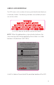
LABELS AND WARNINGS The GFDI comes with a number of warning and identification labels preinstalled by OutBack. The following two labels are installed by the end user or the installer. WARNING! ELECTRIC SHOCK HAZARD IF A GROUND FAULT IS INDICATED, NORMALLY GROUNDED CONDUCTORS MAY BE UNGROUNDED AND ENERGIZED Install this label to the battery enclosure/cabinet.
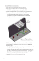
Installation Instructions • Insert the GFDI into the breaker mounting bracket. • Insert and hand-tighten the GFDI’s mounting screws. • CAUTION — overtightening can damage the GFDI. • With all system power off, attach the ground and negative wires to their respective bus bars and to the back of the GFDI. • The ground wire goes to the top of the 0.5 amp breaker. • The negative wire goes to the bottom of the same breaker. (See Figures 1 and 2.) GFDI 0.5 Amp Breaker Figure 1.
Once all breakers are turned on, the 0.5 amp breaker of the GFDI connects the grounding system to the battery negative, while the 80 amp breaker(s) connect the battery to the charge controllers (see Figure 2). • Normal operation of the GFDI is indicated by the green breaker lever in the up/on position. • In normal operation, grounding system is bonded directly to battery negative through the 0.5 amp breaker, and the charge controllers receive battery voltage. • The 0.
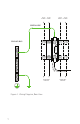
TO CC TO CC #3 BAT+ #1 BAT+ TO CC #2 BAT+ TO CC #4 BAT+ GREEN WIRE 43K OHM 5 WATT GROUND BUS E IR WHITE W TO BATTERY POSITIVE Figure 2.
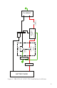
PV ARRAY PV DISCONNECT DC NEGATIVE PV + GND BATTERY + SHUNT DC NEGATIVE CHARGE CONTROLLER #1 TERMINAL BLOCK TERMINAL BUS BAR WHITE DC NEGATIVE GFDI 80 AMP BREAKER GREEN 1/2 AMP GROUND FAULT 43K OHM RESISTOR GROUND BUS BAR DC POSITIVE BUS BAR BATTERY BANK Figure 3.
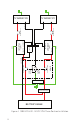
PV + PV + GND BATTERY + DC NEGATIVE CHARGE CONTROLLER #1 TERMINAL BLOCK SHUNT BATTERY + CHARGE CONTROLLER #2 TERMINAL BLOCK DC NEGATIVE TERMINAL BUS BAR PV DISCONNECT DC NEGATIVE DC NEGATIVE PV DISCONNECT GND WHITE DC NEGATIVE GFDI 80 AMP BREAKER GREEN 1/2 AMP GROUND FAULT 43K OHM RESISTOR 80 AMP BREAKER 9 PV ARRAY #1 PV ARRAY #2 GROUND BUS BAR DC POSITIVE BUS BAR BATTERY BANK Figure 4.
PV DISCONNECT DC NEGATIVE PV DISCONNECT DC NEGATIVE DC NEGATIVE PV DISCONNECT DC NEGATIVE PV DISCONNECT GND BATTERY + DC NEGATIVE BATTERY + CHARGE CONTROLLER #3 TERMINAL BLOCK DC NEGATIVE PV + PV + DC NEGATIVE CHARGE CONTROLLER #1 TERMINAL BLOCK SHUNT BATTERY + CHARGE CONTROLLER #2 TERMINAL BLOCK GND BATTERY + PV + CHARGE CONTROLLER #4 TERMINAL BLOCK DC NEGATIVE PV + DC NEGATIVE TERMINAL BUS BAR PV ARRAY #3 PV ARRAY #1 PV ARRAY #2 PV ARRAY #4 WHITE GFDI 80 AMP BREAKER 80 AMP BREA
Corporate Office 19009 62nd Avenue NE Arlington, WA USA (+1) 360-435-6030 www.outbackpower.com European Sales Office C/ Castelló, 17 08830 - Sant Boi de Llobregat BARCELONA, España Phone: +34.93.654.