
User Guide

Installation
900-0111-01-00 Rev A 19
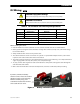
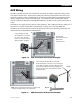
DC Wiring
CAUTION: Equipment Damage
Never reverse the polarity of the battery cables. Always use correct polarity.
CAUTION: Fire Hazard
Always install a breaker, fuse, or protective device to protect the DC system.
Table 4 DC Conductor Size and Torque Requirements
Inverter Nominal DC Amps
(Derated 125%)
Conductor Size
(Minimum)
Breaker Size
GFX1312E
130 70 mm (2/0 AWG or 0.105 in) 175 Adc
GFX1424E
70 70 mm (1/0 AWG or 0.083 in) 125 Adc
GFX1448E
35 50 mm (#1 AWG or 0.066 in) 100 Adc
Terminal Location Torque Requirements
Inverter DC Terminals 4 Nm (35 in-lb)
Battery Terminals See battery manufacturer’s recommendations
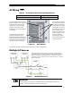
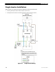
When installing DC cables:
Note minimum sizes in Table 4, but refer to local codes for absolute cable size recommendations.
Battery positive and negative cables should be no longer than 3 meters (10 feet) each, to minimize voltage
loss and other effects.
Always install breakers or fuses on the positive cable.
The cables listed above are for each inverter in a system. In a system with multiple inverters, each inverter
requires its own cables and breakers of the size indicated.
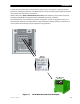
The inverter’s battery terminal is a threaded stud which accepts a ring terminal lug. Use crimped and sealed
copper ring lugs with 0.79 cm (5/16 in) holes, or use compression lugs.
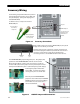
Tie, tape, or twist cables together to reduce self-inductance. Run positive and negative cables through the
same knockouts and conduit.
Make certain the DC breaker is turned to the off position, or the fuse is removed, before proceeding.
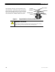
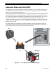
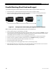
Figure 8 Battery Terminal Covers
If present, remove the battery
terminal covers. These are made of
stiff plastic with a snap-on design.
Remove carefully using a flat
screwdriver inserted into the slots
on the sides of each cover.