GS Load Center Installation Manual
About OutBack Power Technologies OutBack Power Technologies is a leader in advanced energy conversion technology. OutBack products include true sine wave inverter/chargers, maximum power point tracking charge controllers, and system communication components, as well as circuit breakers, batteries, accessories, and assembled systems.
Table of Contents Introduction .......................................................................................................... 3 Welcome to OutBack Power Technologies.................................................................................................................3 GSLC – Components ...........................................................................................................................................................4 GSLC175-120/240 – Components.................
Table of Contents List of Figures Figure 1 Figure 2 Figure 3 Figure 4 Figure 5 Figure 6 Figure 7 Figure 8 Figure 9 Figure 10 Figure 11 Figure 12 Figure 13 Figure 14 Figure 15 Figure 16 Figure 17 Figure 18 Figure 19 Figure 20 Figure 20 Figure 21 Figure 22 Figure 23 Figure 24 Figure 25 Figure 26 Figure 27 Figure 28 Figure 29 Figure 30 Figure 31 Figure 32 Figure 33 Figure 34 Figure 35 Figure 36 Figure 37 Figure 38 Figure 39 Figure 40 Figure 41 Figure 42 2 GS Load Center (GSLC) ..............................
Introduction Welcome to OutBack Power Technologies Thank you for purchasing a GS Load Center (GSLC) from OutBack Power Technologies. The GSLC is part of an OutBack Grid/Hybrid™ system. It is a balance-of-systems enclosure intended to work with Radian Series (GS) inverter/chargers, FLEXmax Charge Controllers, and an OutBack HUB Communications Manager. It is designed in the following configurations: GSLC – GS Load Center for Radian Series. Recommended for custom-built systems.
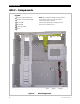
Introduction GSLC – Components Legend 1 Inverter (negative) DC Bus Bars NOTE: The installed Neutral TBB has white insulators. A set of blue insulators is included in the kit for locations where blue is standard. 2 Negative Terminal Bus Bar (TBB) 3 Ground TBB Inverter positive DC bus bars and DC positive bus plate are also included in the kit.
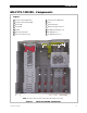
Introduction GSLC175-120/240 – Components Legend 1 Inverter (negative) DC Bus Bars 8 Inverter (positive) DC Bus Bars 2 Negative Terminal Bus Bar (TBB) 9 Shunt 3 Ground TBB 10 AC Circuit Breakers 4 Neutral TBB 11 Maintenance Bypass Interlock 5 PV TBB 12 AC TBB (Inverter Output) L1, L2 6 DC Positive Cable Plate 13 AC TBB (Grid) L1, L2 7 Main Inverter Disconnect(s) 14 AC TBB (Generator) L1, L2 1 8 11 2 10 9 7 3 6 12 13 5 14 4 12 13 14 5 NOTE: The factory wiring has been om
Introduction GSLC175-230 – Components Legend 1 Inverter (negative) DC Bus Bars 8 Inverter (positive) DC Bus Bars 2 Negative Terminal Bus Bar (TBB) 9 Shunt 3 Ground TBB 10 AC Circuit Breakers 4 Neutral TBB 11 Maintenance Bypass Interlock 5 PV TBB 12 AC TBB (Inverter Output) 6 DC Positive Cable Plate 13 AC TBB (Grid) 7 Main Inverter Disconnect(s) 14 AC TBB (Generator) 1 8 11 2 10 9 7 3 6 12 13 14 5 4 5 NOTE: The factory wiring has been omitted from this illustration for clari
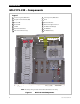
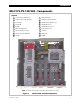
Introduction GSLC175-PV-120/240 – Components Legend 1 Inverter (negative) DC Bus Bars 10 AC Circuit Breakers 2 Negative Terminal Bus Bar (TBB) 11 Maintenance Bypass Interlock 3 Ground TBB 12 AC TBBs (Inverter Output) L1, L2 4 Neutral TBB 13 AC TBBs (Grid) L1, L2 5 PV TBBs 14 AC TBBs (Generator) L1, L2 6 DC Positive Cable Plate 15 PV Input Disconnects 7 Main Inverter Disconnect(s) 16 Shunt Bus 8 Inverter (positive) DC Bus Bars 17 FLEXnet DC 9 Shunt(s) 18 PV GFDI 1 8 11 2
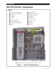
Introduction GSLC175-PV-230 – Components Legend 1 Inverter (negative) DC Bus Bars 10 AC Circuit Breakers 2 Negative Terminal Bus Bar (TBB) 11 Maintenance Bypass Interlock 3 Ground TBB 12 AC TBB (Inverter Output) 4 Neutral TBB 13 AC TBB (Grid) 5 PV TBB 14 AC TBB (Generator) 6 DC Positive Cable Plate 15 PV Input Disconnects 7 Main Inverter Disconnect(s) 16 Shunt Bus 8 Inverter (positive) DC Bus Bars 17 FLEXnet DC 9 Shunt(s) 18 PV GFDI 1 8 2 11 16 10 9 17 7 3 6 18
Planning Tools Required Open-ended wrenches (9/16" and13 mm) Wire cutters/strippers Torque wrenches Assorted insulated screwdrivers Digital Voltmeter (DVM) or regular voltmeter Materials Required Conductors for wiring Conduits Location/Environmental Requirements Indoor mount only Front View Side View 8½" (21.6 cm) deep 16" (40.6 cm) wide 17" (43.
Planning Legend Cable Knockouts (U.S.
Installation Hardware Options The five versions of the GSLC come with different components already installed. GSLC, the “basic” or “empty” version, requires almost all components to be installed if they are needed. Instructions for this product begin on page 13. GSLC175-120/240 and GSLC175-230, the “AC only” versions, require certain components to be installed if they are needed. Instructions for these products begin with the DC shunts, on page 17.
Installation Remove Top Cover To Remove the Top Cover: 1. Remove the four screws; one in each corner. 2. Lift the top off the enclosure. Enclosure with Top Removed Figure 11 Removing the Top Cover from the GSLC Remove Front Door To Remove the Front Door: 1. Open the door to about 90 degrees. 2. Lift the hinges out of the slots at the inside edge. Lift up to remove.
Assembly Remove Interior Cover In order to make any wiring connections or install components, the interior cover must be removed to expose the interior of the enclosure. Remove (x3) To Remove the Interior Cover: 1. Remove the three screws along the top of the enclosure (with one star washer). 2. Remove the three screws along the bottom of the enclosure (with one star washer). 3. Lift the front cover off the enclosure.
Installation Assembling DC Positive Cable Plate The bottom of each DC disconnect is bolted to a bus plate which receives the inverter’s positive (+) battery cables. To assemble the DC Positive Plate: 1. Remove the nuts and other hardware (washer, lock washer, hex nut) from the bottom terminal in the back of each DC disconnect. 2. Place the two disconnects side by side. 3. Orient the DC positive plate so that the three largest holes are at the top. These holes have a diameter of 0.50" (1.3 cm).
Assembly Installing Inverter Positive Bus Bars The GSLC parts kit contains two bus bars, A and B , which attach to the tops of the DC disconnects. These bus bars make the connections with the Radian inverter’s positive DC terminals. Although they have similar shapes, the bus bars are not interchangeable. B A B To assemble the Inverter Positive (+) Bus Bars: 1. Attach bus bar B to the top terminal of the disconnect on the right, using the stud and hardware on the back of the disconnect.
Installation Installing Inverter Main Disconnects To mount the inverter disconnects: Negative Top Bar 1. If the negative top bar is installed, loosen or remove it. 2. Slide the disconnect assembly through the opening in the top of the GSLC and place it behind the premounted bracket. Center the disconnect assembly so that the raised area around the switch protrudes through the bracket. It may be necessary to hold the assembly in place by hand. 3.
Assembly Installing DC Shunts A single 500 Adc/50 mV shunt is included with the GSLC. Up to two more shunts can be installed as needed. These shunts are used in conjunction with the FLEXnet DC battery monitor. See page 25 for more instructions on wiring. To mount DC Shunts: 1. Four mounting holes are located to the lower left of the first shunt. Center each shunt across one pair of mounting holes. These should line up with the mounting holes built into each shunt. 2.
Installation Installing PV and AC Circuit Breakers and GFDI To mount circuit breakers: 1. It may be necessary to remove the knockout from the location where the circuit breaker is to be placed to make room for the circuit breaker to be installed. Be sure to remove any debris that may occur from removing the knockout. 2. Place each circuit breaker behind the premounted rail. Center the device so that the raised area around the switch protrudes through the bracket.
Assembly Mounting on the Inverter IMPORTANT: The Radian inverter and GSLC are intended for indoor use only. Ensure that the mounting surface is strong enough to support the full weight of the Radian inverter/charger and the GSLC. Use a minimum 3/4" (19 mm) sheet of plywood to strengthen the wall surface if required. To mount the GSLC to the Radian inverter: 1. Install the Radian inverter onto the mounting bracket as instructed in the Radian Series Inverter/Charger Installation Manual. 2.
Installation ...continued from the previous page. Bottom Screws Keyhole Slots Keyhole Slots 7. Realign the GSLC along the bottom of the inverter and slide the mounting screws into the keyhole slots. 8. Secure the enclosure to the mounting surface using all four mounting feet holes. 9. Using the bolts provided on the Radian inverter’s battery terminals, connect the terminals to the GSLC’s inverter bus bars. Tighten to the value shown in Table 1 on page 13.
Assembly Mounting FLEXmax Charge Controller The GSLC enclosure accommodates up to two FLEXmax charge controllers and a HUB Communications Manager. NOTE: The following instructions are for the FLEXmax 60 or FLEXmax 80 only. The FLEXmax Extreme charge controller connects directly to the wall and does not need additional brackets. To mount the FLEXmax Charge controller to the side of the GSLC enclosure: NOTE: This illustration shows only brackets for a single charge controller.
Installation Mounting the HUB Communications Manager The GSLC provides mounting holes to support a HUB Communications Manager. To mount the HUB Communications Manager to the side of the GSLC enclosure: 1. Locate the mounting holes on the side of the GSLC enclosure as shown in Figure 8 on page 10. 2. Remove the knockouts and add bushings. 3. Align the HUB (vertically) over the mounting holes with the HUB’s ports facing forward. 4. Insert the mounting screws from the outside into the GSLC enclosure.
Wiring Wiring Table 2 Terminal Bus Bar (TBB) Wire Size and Torque Requirements Conductor Size AWG #14 – #10 #8 #6 – #3 #2 #1 – 1/0 mm2 2.5 – 4 6 – 10 16 – 25 35 50 Torque Requirements In-lb 20 25 35 40 50 Nm 2.3 2.8 4.0 4.5 5.7 Grounding WARNING: Shock Hazard The unit must be connected to a grounded, permanent wiring system. If a bond is made between neutral and ground, make sure only one bond is present in the AC system at any time. The GSLC comes equipped with a neutral-ground bond.
Installation Bonding All GSLC models are equipped with a mechanical bond between AC neutral and ground. All models that do not include the GFDI are also equipped with a mechanical bond between DC negative and ground. These can be useful in stand-alone systems where no other bond is provided. If other bonds are present, or if the GFDI is installed later, the GSLC bonds need to be removed. WARNING: Shock Hazard GSLC models purchased with the OutBack GFDI do not have a bond between negative and ground.
Wiring DC Wiring WARNING: Shock Hazard Ensure all circuit breakers or disconnect devices are turned off or disconnected before connecting any wires. Inverter Wiring The DC disconnects are connected directly to the inverter using bus bars during the process of mounting. See page 20 for more information. Battery Wiring The Radian inverter requires two positive (+) and two negative (–) cables for proper installation.
Installation Installing the FLEXnet DC The OutBack FLEXnet DC (FNDC), or a similar battery monitor, may be added to the GSLC for observing DC current flow and providing battery state-of-charge information. HUB port Wiring block Figure 26 FNDC and Wiring Block To install the FNDC : 1. Assemble the FNDC wiring as shown in the manual for the FNDC. Attach sense wires to FNDC wiring block and plug it into the FNDC. Mounting screws Plug the CAT5 cable into the port labeled HUB. 2.
Wiring DC Devices In addition to inverter or PV connections, other devices may be connected to the GSLC, such as DC loads or sources. The wiring on these devices will vary with the application. In most cases the device will have a separate circuit breaker which is mounted on the rail as shown on page 18. It will be wired into the battery system using the existing bus bars or shunts. The number and location of these connections will vary with the options or accessories installed.
Installation Negative TBB DC Positive (+) plate Shunt GFDI PV Disconnect PV Positive (+) TBB Figure 28 PV Connections in the GSLC Battery Positive (+) PV Positive (+) PV+ PV Negative (–) Figure 29 28 PV– BAT– BAT+ Battery Negative (–) PV Connections in the FLEXmax Charge Controller 900-0123-01-00 Rev B
Wiring AC Wiring WARNING: Shock Hazard Ensure all circuit breakers or disconnect devices are turned off or disconnected before wiring. Make certain the inverter and other active devices are turned off or disabled before wiring. Split-Phase Wiring The GSLC can have multiple terminal bus bars for multiple AC connections. Because the Radian inverter possesses two sets of AC input connections and one set of output connections, up to three TBB sets are available.
Installation Bypass Assembly Bypass switching can be used when the inverter is shut down for maintenance. This topic is discussed more beginning on page 34. The GSLC can be equipped with the GS-IOB-120/240VAC bypass assembly. The instructions on this page are for making external connections to the bypass assembly after installation. (The installation wiring for the GS-IOB-120/240VAC is described on page 33.
Wiring Single-Phase Wiring The GSLC allows multiple terminal bus bars (TBB) for multiple AC connections. Because the Radian inverter possesses two sets of AC input connections and one set of output connections, three terminal bus bars are available for hot connections, as well as one neutral bus bar. The hot bus bars have brown insulators in 230 Vac models. A blue bus bar for neutral connections is also available. The TBB on the left is generally used for the inverter’s AC output connections.
Installation Bypass Assembly Bypass switching can be used when the inverter is shut down for maintenance. This topic is discussed more beginning on page 34. The GSLC can be equipped with the GS-IOB-230VAC bypass assembly. The instructions on this page are for making external connections to the bypass assembly after installation. (The installation wiring for the GS-IOB-230VAC is described on on page 34.
Wiring Wiring the AC Bypass Assembly The GSLC175-120/240, GSLC175-PV-120/240, GSLC175-230, and GSLC175-PV-230 each come equipped with a maintenance bypass assembly. Alternately, they can be equipped with a bypass assembly using the GS-IOB-120/240VAC or GS-IOB-230VAC accessory kit as appropriate. The accessory kit should be installed according to its own instructions. Once installed, it can be wired by following the steps shown in Figure 34 or Figure 35 .
Installation To wire the GS-IOB-230VAC after installation: 1. 2. On the disconnect for the AC source that will be used during bypass, install a wire from the left side as shown by 1 . Connect it to the input bypass switch as shown by 2 . Output Inverter Bypass AC Source 4 2 3 1 Install a wire on the right side of the input bypass switch as shown by 3 . Connect it to the right side of the output switch as shown by 4 .
Wiring In Figure 36, when Switch 1 is on (normal operation), the inverter’s output sends power to the loads. Switch 2 is off, preventing the inverter from sending power back to the AC source (backfeeding). When Switch 2 is on (bypass operation), the AC source sends power directly to the loads. Switch 1 is off, removing the inverter’s output from the loads. This also prevents the AC source from backfeeding the inverter. With the inverter removed from the circuit, maintenance can be performed as necessary.
Installation Input Wiring External Bypass Device Output Wiring Inactive Radian Inverters AC Loads AC Source GSLC Bypass Devices (must be removed if installed previously) Figure 38 36 Bypass Switching for Multiple Inverters (split-phase) 900-0123-01-00 Rev B
Wiring Wiring Diagrams Figure 39 900-0123-01-00 Rev B Wiring Diagram – GSLC175-120/240 37
Installation Figure 40 38 Wiring Diagram – GSLC175-PV-120/240 with FNDC 900-0123-01-00 Rev B
Wiring Figure 41 900-0123-01-00 Rev B Wiring Diagram – GSLC175-230 39
Installation Figure 42 40 Wiring Diagram – GSLC175-PV-230 with FNDC 900-0123-01-00 Rev B
Specifications Electrical Specifications Table 3 Electrical Specifications Specification Measurement Maximum Input Voltage Maximum Input Current Operating Frequency Range 600 Volts 500 Amps 50/60 Hz to DC Mechanical Specifications Table 4 Mechanical Specifications Specification Measurement Dimensions (H x W x D) Shipping Dimensions (L x W x H) Weight Shipping Weight Enclosure Type 17" x 16" x 8.5" (43.2 cm x 40.6 cm x 21.6 cm) 23.25" x 20.5" x 13.25" (59.1 cm x 52.1 cm x 33.7 cm) 26 lb (11.
Specifications Definitions The following is a list of initials, terms, and definitions used in conjunction with this product. Table 5 Term AC 42 Terms and Definitions Definition Alternating Current; refers to voltage produced by the inverter, utility grid, or generator AUX One of several auxiliary outputs on the GS inverter/charger. CSA Canadian Standards Association; establishes Canadian national standards and the Canadian Electrical Code, including C22.1 and C22.
Index A F AC Bypass Assembly....................................30, 32, 33, 34 AC Circuit Breakers............................................................18 AC Terminal Bus Bars.................................................29, 31 AC Wiring ...............................................................29, 37, 39 120/240 Vac ............................................................29, 37 230 Vac .....................................................................31, 39 Additional Components.....
Index P Torque Requirements ......................................................13 Positive Bus Hardware .......................................13, 14, 15 PV Circuit Breakers ............................................................18 PV Wiring..............................................................................27 U R W Regulatory............................................................................41 Wire Size and Torque Requirements...........................
THIS PAGE INTENTIONALLY LEFT BLANK.
Corporate Headquarters 5917 – 195th St NE Arlington, WA 98223 USA +1.360.435.6030 900-0123-01-00 Rev B European Office Hansastrasse 8 D-91126 Schwabach, Germany +49.9122.79889.