
Outback Power QuickStart Guide

Masters of the Off-Grid.™
First Choice for the New Grid.
900-0159-01-00 Rev B.vsd\Page-1\2014-01-30
©2013 OutBack Power Technologies. All Rights Reserved.
Setup and Programming
Note: See the MATE3
manual for details on
generator control.
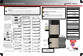
Quick Start Guide RADIAN Series
HUB 10.3
Communications
Manager
MATE3
System
Display and
Controller
Radian Inverter/Charger
GS Load Center
(GSLC)
FM80 Charge
Controllers
(x2)
WARNING: Fire/Explosion Hazard
Do not place combustible or flammable materials within 3.7 m (12 feet) of
the equipment. This unit employs mechanical relays and is not ignition-
protected. Fumes or spills from flammable materials could be ignited by sparks.
WARNING: Personal Injury
Use safe lifting techniques and standard safety equipment when working with
this equipment.
IMPORTANT:
Clearance and access requirements may vary by location. Maintaining a 90-cm
(36") clear space in front of the system for access is recommended.
Consult local electric code to confirm clearance and access requirements
for the specific location.
CAUTION: Equipment Damage
These procedures should be done by a qualified installer who is trained on programming inverter power systems.
Failure to set accurate parameters for the system could potentially cause equipment damage. Damage caused by
inaccurate programming is not covered by the limited warranty for the system.
IMPORTANT
Check the firmware revision of all OutBack devices before use. The Radian inverter and MATE3 system display may not
communicate or operate correctly unless their firmware is above a specified revision number.
For model GS7048E, the firmware must be revision 001.005.xxx or higher with a MATE3 revision of 002.010.xxx or higher.
For model GS3548E, the firmware must be revision 001.005.xxx or higher with a MATE3 revision of 002.017.xxx or higher.
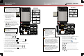
The MATE3 Configuration
Wizard allows quick setup of
parameters that apply to all
systems. The Configuration
Wizard is reached from the
MATE3 Main Menu as shown
to the right.
The firmware revision of all
devices can be confirmed by
navigating from the MATE3
Main Menu as shown below.
Upgrades to the firmware
revision can be downloaded
from the OutBack website
www.outbackpower.com.
IMPORTANT:
Not intended for use with
life support equipment.
Contact Technical Support:
Telephone: +1.360.618.4363
Email: Support@outbackpower.com
Website: www.outbackpower.com
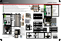
AC Source
Utility Grid or
AC Generator
Main Electrical Panel (or overcurrent
device for the AC source)
Electrical Distribution Subpanel
(Load Panel)
Photovoltaic (PV) Array
Battery Bank
Customer-Supplied Components
Optional OutBack Components
FLEXnet DC Monitor (FN-DC)
Remote Temperature Sensor (RTS)
Charge Controller
FLEXmax 80 depicted
(with FW-CCB2
mounting bracket)
PV Combiner Box PV12 depicted
Communications
Manager
HUB10.3 depicted
EnergyCell depicted
Inverter/Charger
GS Load Center
System Display
and Controller
MATE3 depicted
(with FW-MB3
mounting bracket)
GS7048E
GS3548E
Radian System Products
Major Components
GSLC175-PV-230
GSLC175PV1-230
(both depicted)
S
Firmware Revision
Configuration Wizard
Off Grid
Grid Tied Backup
This advances the display to the
Setup Complete screen.
C
C
C
S
S
S
C
This advances the display to the
Setup Complete screen if the
FLEXnet DC is not installed. If the
FLEXnet DC is installed, the display
advances to the Shunt screens.
If FN-DC is installed...
If FN-DC is installed...
If FN-DC is installed...
Generator Installed Y
Generator Type AC Size 5.0 kW
Generator Start Manual
AUX Output Device Port 1
Back Continue
New Configuration >>
Existing Configuration >>
Restore Configuration >>
System Type Grid Tied
System Voltage 48 VDC
Array Wattage 1000
Battery Type FLA Capacity 500 Ah
Back Continue
Absorb Voltage 57.6 VDC Time 1.0
Float Voltage 54.4 VDC Time 1.0
Equalize Voltage 60.0 VDC Time 3.0
Re-Float Voltage 44.0 VDC
Back Continue
New Configuration Initialized
Back Continue
Shunt A
Connection Inverter
Back Continue
Shunt B
Connection Charge Controller
Back Continue
Shunt C
Connection Charge Controller
Back Continue
Period 1 Enable N
Weekday Use 0:00 Drop 0:00
Weekend Use 0:00 Drop 0:00
Back Continue
Period 2 Enable N
Weekday Use 0:00 Drop 0:00
Back Continue
Period 3 Enable N
Weekday Use 0:00 Drop 0:00
Back Continue
Shunt A
Connection Inverter
Back Continue
Shunt B
Connection Charge Controller
Back Continue
Shunt C
Connection Charge Controller
Back Continue
Mode Disabled
Grid Connect 48.0 VDC Delay 60 Min
Grid Disconnect 52.0 VDC Delay 60 Min
Grid Connect SOC 60% Disconnect SOC 95%
Back Continue
Shunt B
Connection Charge Controller
Back Continue
Shunt C
Connection Charge Controller
Back Continue
Period 3 Enable N
Weekday Use 0:00 Drop 0:00
Back Continue
Mode Disabled
Grid Connect 48.0 VDC Delay 60 Min
Grid Disconnect 52.0 VDC Delay 60 Min
Grid Connect SOC 60% Disconnect SOC 95%
Back Continue
Period 1 Enable N
Weekday Use 0:00 Drop 0:00
Weekend Use 0:00 Drop 0:00
Back Continue
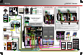
Generator Installed N
Generator Type AC Size 5.0 kW
Generator Start Manual
AUX Output Device Port 1
Back Continue
AC Output Voltage 230 VAC
AC Phase Single
AC Input Breaker Size 50 A
Maximum Output Load 30 A
Back Continue
Period 2 Enable N
Weekday Use 0:00 Drop 0:00
Back Continue
Generator Installed N
Generator Type AC Size 5.0 kW
Generator Start Manual
AUX Output Device Port 1
Back Continue
Absorb Voltage 57.6 VDC Time 1.0
Float Voltage 54.4 VDC Time 1.0
Equalize Voltage 60.0 VDC Time 3.0
Re-Float Voltage 44.0 VDC
Back Continue
AC Output Voltage 230 VAC
AC Phase Single
AC Input Breaker Size 50 A
Maximum Output Load 30 A
Back Continue
System Type Backup
System Voltage 48 VDC
Array Wattage 1000
Battery Type FLA Capacity 500 Ah
Back Continue
Shunt A
Connection Inverter
Back Continue
AC Output Voltage 230 VAC
AC Phase Single
AC Input Breaker Size 50 A
Maximum Output Load 30 A
Back Continue
Absorb Voltage 57.6 VDC Time 1.0
Float Voltage 54.4 VDC Time 1.0
Equalize Voltage 60.0 VDC Time 3.0
Re-Float Voltage 44.0 VDC
Back Continue
System Type Off Grid
System Voltage 48 VDC
Array Wattage 1000
Battery Type FLA Capacity 500 Ah
Back Continue
Settings >>
Configuration Wizard >>
Device Data Logs >>
Event Logs >>
Firmware Update >>
System >>
Inverter >>
Charge Controller >>
Battery Monitor >>
MATE3 >>
System
System Information >>
Save / Store Information >>
Firmware Version >>
Date and Time >>
LCD Display >>
MATE3 002.017.018
1: GS7048E 001.005.002
2: GS7048E 001.005.002
Settings >>
Configuration Wizard >>
Device Data Logs >>
Event Logs >>
Firmware Update >>
Settings
Configuration Wizard
New Configuration
!