Radian Series Inverter/Charger GS8048 Operator’s Manual
About OutBack Power Technologies OutBack Power Technologies is a leader in advanced energy conversion technology. Outback products include true sine wave inverter/chargers, maximum power point tracking charge controllers, and system communication components, as well as circuit breakers, accessories, and assembled systems. Contact Information Telephone: +1.360.435.6030 +1.360.618.4363 (Technical Support) +1.360.435.
Important Safety Instructions READ AND SAVE THESE INSTRUCTIONS! This manual contains important safety instructions for the Radian Series Inverter/Charger. Read all instructions and cautionary markings on the inverter and on any accessories or additional equipment included in the installation. Failure to adhere to these instructions could result in severe shock or possible electrocution. Exercise extreme caution at all times to prevent accidents.
Important Safety Instructions Table 1 Terms and Definitions Term Definition DVM Digital Voltmeter ETL Electrical Testing Laboratories; short for the company ETL Semko; refers to a certification issued by ETL to OutBack products indicating that they meet certain UL standards FCC Federal Communications Commission GND Ground; a permanent conductive connection to earth for safety reasons; also known as Chassis Ground, Protective Earth, PE, Grounding Electrode Conductor, and GEC Grid-interactive, gri
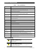
Table of Contents Important Safety Instructions ........................................................................1 Audience .................................................................................................................................................................................1 Symbols Used ........................................................................................................................................................................1 Definitions........
Table of Contents Warning Messages............................................................................................................................................................ 40 Disconnect Messages ...................................................................................................................................................... 42 Sell Status ....................................................................................................................................
Introduction Welcome to OutBack Power Technologies Thank you for purchasing the OutBack Radian Series Inverter/Charger. This product offers a complete power conversion system between batteries and AC power. It can provide backup power, sell power back to the utility grid or provide complete stand-alone off-grid service.
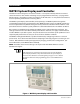
Introduction MATE3 System Display and Controller The Radian inverter/charger has no external controls. It can operate normally without an external control or interface. Basic modes and settings are pre-programmed at the factory. (See page 47 for default settings.) The Radian inverter has no display or LED indicators. It is not possible to monitor its status or operating mode without a metering device.
Commissioning Functional Test WARNING: Shock Hazard and Equipment Damage It is necessary to remove the cover of the Radian inverter to perform these tests. The components are close together and carry hazardous voltages. Use appropriate care to avoid the risk of electric shock or equipment damage. Pre-startup Procedures 1. 2. 3. 4. Ensure all DC and AC overcurrent devices are opened, disconnected, or turned off. Double-check all wiring connections.
Commissioning After programming (if any) is completed, perform the following steps: 1. If other inverters are on the system, use a DVM to verify correct voltage from the L1 OUT terminal on one inverter to the next. When stacked in parallel, the wires from one inverter to the next should read 0 Vac (although individually they should still read 120 Vac with respect to neutral). Repeat for the L2 OUT terminal. 2. Close the AC output circuit breakers.
Operation Input Modes The Radian inverter has two sets of input connections for multiple AC sources. (See the Radian Series Inverter/Charger Installation Manual for more information.) With the MATE3, each input can be programmed to a particular operating mode. Six modes are available, each with certain advantages which make it ideal for a particular application. Some modes contain functions unique to that mode. Both of the Radian’s inputs can be programmed for separate modes.
Operation NOTES: The Support, Offset, and grid-interactive functions of the Radian are unavailable in this mode. Any AC fluctuations that are accepted by the inverter will be transferred to the output. The loads will be exposed to these fluctuations. It may not be advisable to install senstive loads under these conditions. In this mode, the Radian inverter’s maximum charge rate is limited to 20 Aac (80 Adc). While charging, the charger will not go silent (see page 22).
Operation Grid Tied IMPORTANT: Selling power to the utility company requires the authorization of the local electric jurisdiction. The method used by the local utility company to accommodate this will depend on their policies on this issue. Some may pay for power sold; others may issue credit. Some policies may prohibit the use of this mode altogether. Please check with the utility company and obtain their permission before using this mode.
Operation The grid-interactive function can only operate while the utility grid power is stable and within specific limits. If the AC voltage or frequency vary outside these limits, the inverter will stop selling. If the inverter stops selling, the MATE3 will show the reason. Sell Status messages are listed on page 43. If the AC voltage or frequency vary outside the maximum limits, the inverter will also disconnect from the utility grid.
Operation Backup This mode is intended for systems that have utility grid available as the primary AC source. This source will pass through the Radian inverter’s transfer circuit and will power the loads unless utility power is lost. If utility grid power is lost, then the Radian inverter will supply energy to the loads from the battery bank. When the utility power returns, it will be used to power the loads again.
Operation will then enter Silent (see page 22) and continue repeating this part of the charging cycle until it disconnects from the utility grid. If the reconnection was triggered by the Rebulk voltage setting, the inverter will require the charger to pass through the entire charge cycle, including the Absorb Voltage, Absorb Time, Float Voltage, and Float Time settings (as well as Offset). The inverter will continue repeating the Float part of the charging cycle until it disconnects from the utility grid.
Operation Functions The items in this section are states of operation common to all Radian inverters. These functions can be used in most or all of the input modes described in the preceding section. Some can be manually selected or enabled; others are automatic. All items identified as settable or adjustable have set points which can be accessed using the remote system display. (See the MATE3 Owner’s Manual for instructions on locating these set points.
Operation Search An automated search circuit is available to minimize the power draw when no loads are present. When enabled, the inverter does not always deliver full output. The output is reduced to brief pulses with a delay between them. These pulses are sent down the output lines to see if a resistance is present. Basically, the pulses “search” for a load. If a load is detected on either the L1 or L2 outputs, the inverter’s output increases to full voltage so that it can power the load.
Operation AC Current Settings The AC current settings control the amount of current that the inverter draws from the source(s). The amount of current is controlled by the grid or generator limit settings. These settings should be adjusted to match the size of the input circuit breaker. In the MATE3 system display, if the Inverter Input Priority or AC Input and Current Limit menus are set to Grid, the inverter uses the grid settings. If the menus are set to Gen, the inverter uses the generator settings.
Operation Generator A generator should be sized to provide enough power for all inverters, both for loads and for battery charging. It is usually recommended that the generator be sized at twice the wattage of the inverter system. Many generators may not be able to maintain AC voltage or frequency for long periods of time if they are loaded more than 80% of rated capacity. The generator is required to have a stable output before its power is accepted by the inverter.
Operation Offset This function is designed to use excess battery energy to power the loads, even when an AC source is present. This allows the system to take advantage of renewable energy sources, in effect “offsetting” dependence on the AC source. When a renewable source of energy raises the batteries above a designated reference point (or “target”), the inverter exports power to the loads in order to bring the voltage back down or to prevent it from rising further.
Operation Battery Charging IMPORTANT: Battery charger settings need to be correct for a given battery type. Always follow battery manufacturer recommendations. Making incorrect settings, or leaving them at factory default settings, may cause the batteries to be undercharged or overcharged. The inverter uses a “three-stage” battery charging process. The three stages are Bulk, Absorption, and Float. These stages follow a series of steps, which are shown on graphs (see page 21).
Operation Voltage Absorption Set Point Absorption Float Set Point Sell Set Point Float Timer Offset Re-Float Set Point No Charge Offset Silent Float Silent Bulk Time Figure 3 Charging Stages Over Time1 Voltage Absorption Set Point Absorption Float Set Point Float Bulk No Charge No Charge Time Figure 4 Charging Stages Over Time1 (Generator mode) well, even if their timers have not expired. The remaining time for the slaves will be retained in the timer for each inverter.
Operation This setting is typically lower than the Float voltage setting. Although the batteries are not discharged, they are maintained at a somewhat lower voltage so that the maximum amount of power can be exported. It is recommended that this item be set at the batteries’ natural rest voltage. In the Grid Tied input mode, excess power is sent first to any loads on the inverter’s output, using the Offset function (see page 19).
Operation The unit will continue cycling between Float and Silent for as long as the AC source is present. However, if excess DC power is available and the battery voltage rises above the Sell Voltage set point, the unit can resume Offset activity as described on page 21. The unit can only enter Offset when none of the timers are active. If any of the timers have accumulated time while in Silent, the unit will enter the highest stage with accumulated time and proceed from that point.
Operation The Absorption timer continues this behavior even if the charger is still on. For example, if the charger is in Float stage and there is a significant battery drain, the charger may not be able to maintain the batteries at the Float voltage. Once the batteries fall below the Rebulk point, the Absorption timer will begin accumulating time. (However, the accumulation will be minor, as this will also cause the charger to re-enter the Bulk stage.
Operation Conversely, when batteries are warmer than room temperature, the electrolyte reaction is somewhat hyper-reactive. It takes less energy than usual to charge them. Delivering the full (room-temperature) amount of energy would overcharge them and can be hard on them over time. The Radian inverter, when equipped with the Remote Temperature Sensor (RTS) will compensate for changes in temperature.
Operation Multiple-Inverter Installations (Stacking) Multiple inverters in a single system can support larger loads than a single inverter can handle. Installing inverters in this configuration is called “stacking”. Stacking inverters does not refer to physically placing one on top of another. It refers to how they are wired within the system and then programmed to coordinate activity. Stacking allows all units to work together as one system.
Operation In parallel stacking, two or more inverters are stacked to create a single, common 120/240 Vac bus. The master provides the primary output. The slaves are connected to the same output and assist the master. The slave inverters can be programmed to activate on demand, reducing idle-power consumption. They will remain off until the loads exceed a certain threshold. A two-inverter system can continuously power 16 kVA of loads. Up to ten inverters may be installed in a parallel arrangement.
Operation Power Save Levels Each inverter consumes approximately 30 watts of idle power while it remains on, even if it is not actively inverting or charging. The Power Save function allows the option to put some or all slave inverters into a quiescent state known as Silent mode. This mode minimizes the inverter’s idle consumption. The inverters will come on again when the loads require power. (The term “Silent” is also used in the context of battery charging. See page 22.
Operation Auxiliary Terminals The Radian inverter has two sets of terminals which can respond to different criteria and control many functions. The 12V AUX terminals provide a 12 Vdc output that can deliver up to 0.7 Adc to control external loads. The RELAY AUX terminals are “dry” relay contacts with no voltage. Each set of terminals has its own set of programmed criteria. Each has identical options available.
Operation Gen Alert is used as a controller for an AC generator with a remote start feature, although it has limited functionality. (The generator recharges batteries using the inverter’s battery charger.) When the battery voltage falls to a low set point for a settable delay, the AUX output is activated. The AUX output is used to energize a relay. The relay contacts then activate the remote start/stop circuit on the generator. This is illustrated in the Radian Series Inverter/Charger Installation Manual.
Operation Source Status enables the AUX output whenever the inverter accepts an AC source. It can activate a light or alarm to show that the utility grid is present or that a generator has started. Alternately, it could be used to show that the source has disconnected. This function does not have settable parameters. AC Divert enables the AUX output to divert excess renewable energy to an AC load, usually an AC device powered by the inverter itself.
Operation System Display-Based Functions Advanced Generator Start (AGS) As noted under the Gen Alert feature (see page 31), the system is capable of starting a generator. Gen Alert simply starts and stops the generator based on battery voltage. For more advanced control, the inverter system can use the Advanced Generator Start (AGS) feature, which runs through the entire three-stage charging cycle. It can start according to battery voltage, inverter load, time of day, and other criteria.
Troubleshooting Basic Troubleshooting Table 2 is organized in order of common symptoms, with a series of possible causes. Each possible cause also shows possible troubleshooting remedies, including system display checks where appropriate. In troubleshooting, AC voltages can be measured at this series of test points using a narrow probe Figure 8 AC Test Points Table 2 Symptom No AC output (will not invert). One or more inverters will not invert while others do (in multi-inverter system).
Troubleshooting Table 2 Symptom Will not connect to the AC source. 34 Troubleshooting Possible Cause Possible Remedy No AC input. Check the AC voltage on the inverter’s input test points. (See page 33.) If not present, the problem is external. If present, the inverter could be damaged. Contact OutBack Technical Support (see inside front cover of this manual). AC input not connected on both L1 and L2. Check the AC voltage on the inverter’s input test points. (See page 33.
Troubleshooting Table 2 Symptom Troubleshooting Possible Cause Possible Remedy Charge complete or nearly complete. Check the DC voltage and charging stage using the MATE3, if present. Confirm with DC voltmeter. MATE3’s DC meter reads significantly higher than actual battery voltage. Check the DC voltage on the inverter’s DC terminals. If different from the MATE3 reading, the inverter could be damaged. Otherwise, check the DC voltage on batteries with a voltmeter.
Troubleshooting Table 2 Symptom Possible Cause Troubleshooting Possible Remedy Reduced power sold AC source voltage is driven high When the inverter senses a rise in grid voltage while selling, it to the utility grid. when the inverter sells large reduces the sell current, to avoid forcing the voltage to amounts of power. unacceptable levels. Check AC input voltage while selling. The inverter may be behaving correctly. Erratic AC source voltage. Check AC voltage on the inverter’s input test points.
Troubleshooting Table 2 Symptom Inverter hums loudly. System display may show messages for high battery voltage, low battery voltage, or backfeed error. Generator, external fan, etc. fails to start when triggered by AUX output. Troubleshooting Possible Cause Possible Remedy Inverter output is being fed with an external AC source that is out of phase. Disconnect AC output wires. Turn the inverter off and then on. If the problem clears, reconnect the AC output wires.
Troubleshooting NOTES: 38 900-0020-01-00 Rev A
Troubleshooting Error Messages An Error is caused by a critical fault. In most cases when this occurs, the unit will shut down. The MATE3 system display will show an Event and a specific Error message. This screen is viewed using the MATE3 Home screen’s soft keys. (See the MATE3 manual for more instructions.) One or more messages will display Y (yes). If a message says N (no), it is not the cause of the error.
Troubleshooting Warning Messages A Warning message is caused by a non-critical fault. When this occurs, the unit will not shut down, but the MATE3 system display will show an Event and a specific Warning message. This screen is viewed using the MATE3 Home screen’s soft keys. (See the MATE3 manual for more instructions.) One or more messages will display Y (yes). If a message says N (no), it is not the cause of the warning.
Troubleshooting Table 4 Warning Troubleshooting Message Definition Possible Remedy Fan Failure The inverter’s internal cooling fan is not operating properly. Lack of cooling may result in derated inverter output wattage. Turn the battery disconnect off, and then on, to determine if the fan self-tests. After this test, contact OutBack Technical Support for the next step. (The next step will depend on the results of the test.
Troubleshooting Disconnect Messages Disconnect messages explain the reason that the inverter rejected an AC source. The unit returns to inverting mode if turned on. This screen is viewed using the AC INPUT hot key on the MATE3. (See the MATE3 manual for more instructions.) One or more messages will display Y (yes). If a message says N (no), it is not the cause of the disconnect. The MATE3 system display may generate a concurrent Event and Warning message following the disconnect. (See previous page.
Troubleshooting Sell Status Sell Status messages describe conditions relating to the inverter’s grid-interactive mode. This screen is viewed using the MATE3 Home screen’s soft keys. (See the MATE3 manual for more instructions.) One or more messages will display Y (yes). If a message says N (no), it is not the cause of the disconnect. If the inverter has stopped selling or charging unexpectedly, this screen may identify the reason.
Troubleshooting NOTES: 44 900-0020-01-00 Rev A
Specifications Specifications for Model GS8048 Table 7 Electrical Specifications for Model GS8048 Specification Value Nominal DC Input Voltage Continuous Output Power at 25°C AC Output Voltage AC Output Frequency Continuous AC Output Current at 25°C Waveform CEC Weighted Efficiency Total Harmonic Distortion (maximum) Harmonic Distortion (maximum single voltage) Output Voltage Regulation Maximum Output Current (1 ms peak) Maximum Output Current (100 ms RMS) Overload Capability (100 ms surge) Overload Cap
Specifications Environmental Specifications Table 9 Environmental Specifications for All Models Specification Value Rated Temperature Range (meets all specifications) 32°F to 122°F (0°C to 50°C) –40°F to 140°F (–40°C to 60°C) –40°F to 140°F (–40°C to 60°C) Operational Temperature Range (functions, but does not necessarily meet all specifications) Storage Temperature Range Regulatory Specifications Canadian Electrical Code, Part I (CSA C22.2 No. 107.
Specifications The acceptance ranges are selected using the system display. In the MATE3, the options are IEEE and user. The IEEE option allows a range of 108 – 132 Vac at 59.3 – 60.5 Hz The user option does not have a fixed voltage setting. It follows the upper and lower limit settings in the Grid AC Input Mode and Limits menu. The default is a range of 108 – 132 Vac. Reconnection delay is 6 seconds. Sell delay is 5 minutes. These settings are not adjustable.
Specifications Table 11 Field Item Aux Control Aux Mode Auxiliary Output (Load Shed) ON: Batt > (Load Shed ON) Delay (Load Shed) OFF: Batt < (Load Shed OFF) Delay (Gen Alert) ON: Batt < (Gen Alert ON) Delay (Gen Alert) OFF: Batt > (Gen Alert OFF) Delay (Vent Fan) ON: Batt > (Vent Fan) Off Delay (DC Divert) ON: Batt > (DC Divert ON) Delay (DC Divert) OFF: Batt < (DC Divert OFF) Delay (AC Divert) ON: Batt > (AC Divert ON) Delay (AC Divert) OFF: Batt < (AC Divert OFF) Delay Aux Control Aux Mode GS8048 Inve
Product Registration The purchase of an OutBack Power Technologies product is an important investment. Registering the products will help us maintain the standard of excellence you expect from us in terms of performance, quality and reliability. Please take a moment to register and provide us with some important information. Registration can be done as follows: Go to the following web site. 10Hhttp://www.outbackpower.
Product Registration INSTALLATION INFORMATION System Install/Commission Date System Array Size System Array Nominal Voltage Type of PV Modules System Battery Bank Size (Amp-Hours) Brand and Model of Batteries Does this system include an auxiliary AC generator? If yes, please specify brand and model of generator INSTALLER INFORMATION Contractor Number Installer Name Installer Address Installer City, State, Postal or Zip Code, Country Installer Telephone/E-mail Please check ALL factors affecting purchase d
Warranty 5-Year Limited Warranty for Radian Products OutBack Power Technologies, Inc. (“OutBack”) provides a five-year (5) limited warranty (“Warranty”) against defects in materials and workmanship for its Radian Series products (“Product”) if installed in fixed location applications. The term of this Warranty begins on the Product(s) initial purchase date, or the date of receipt of the Product(s) by the end user, whichever is later.
Warranty How to Arrange for Warranty Service During the warranty period beginning on the invoice date, OutBack Power Technologies will repair or replace products covered under this limited warranty that are returned to OutBack Power Technologies’ facility or to an OutBack Power Technologies authorized repair facility, or that are repaired on site by an OutBack Power Technologies authorized repair person. IMPORTANT: For full Warranty description, see previous page.
Warranty Returning Product to OutBack After receiving the RMA number, the customer must pack the Product(s) authorized for return, along with a copy of the original purchase invoice and warranty certificate, in the original Product shipping container(s) or packaging providing equivalent or reasonable protection. The RMA number must be written on the outside of the packaging where it is clearly visible. If Product is within the warranty period, OutBack will cover pre-paid shipping with prior arrangement.
Warranty THIS PAGE INTENTIONALLY LEFT BLANK.
Index 1 D 10-year Warranty ...............................................................50 12V AUX................................................................................30 Default Settings .................................................................47 Definitions..............................................................................2 Design ...................................................................................16 Disconnect...............................................
Index I IEEE .................................................................................... 2, 46 Input Modes ........................................7, 11, 17, 20, 22, 23 Input Priorities ....................................................................17 Inverting ...............................................................................16 L LBCO (Low Battery Cut-Out) ..........................................16 Levels, Power Save ...........................................................
THIS PAGE INTENTIONALLY LEFT BLANK.
North America: 5917 – 195th St NE, #7 Arlington, WA 98223 USA +1.360.435.