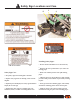
Effective January, 2003 Last Edit May, 2003 DOM-OBK03 Rev.
TABLE OF CONTENTS Introduction . . . . . . . . . . . . . . . . . . . . . . . . . . . . . . . . . . . 1 Definitions of Safety and Service Statements . . . . . . . . 2 Specifications . . . . . . . . . . . . . . . . . . . . . . . . . . . . . . . . . 3 Safety Sign Locations and Care . . . . . . . . . . . . . . . . . . 4 Safety Information . . . . . . . . . . . . . . . . . . . . . . . . . . . . . 5 Installation . . . . . . . . . . . . . . . . . . . . . . . . . . . . . . . . . . . . 6 Tractor Preparation . . . .
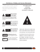
Definitions of Safety and Service Statements THIS SYMBOL MEANS All safety statements in this manual, as well as those - ATTENTION! found on safety decals, are preceded by the following - BECOME ALERT! warning symbols. Carefully read and follow the instruc- - YOUR SAFETY IS INVOLVED! tions provided. Indicates an imminently hazardous situation that, if not avoided, will result in death or serious injury.
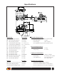
Specifications Dimensions: Inch (mm) (A) (B) (C) (D) (E) (F) (G) (H) (I) (J) (K) (L) (M) (N) (O) 11.5 (292) 12.25 (311) 14.25 (362) 1.5 - 2.0 (38 - 51) 2.25 - 3.25 (64 - 83) 1.75 (46) 10.25 (260) 6.5 (165) 21 (534) 2.0 (51) 3.0 (76) ±10.0 (±254) 4.0 (102) 3.25 (83) 1.67 (42) Min. Long Drop Clearance Max. Short Drop Clearance Min. Mounting Clearance Tractor Drawbar Thick.
! Safety Sign Locations and Care B C A C P/N 60257 A P/N DEC-MT4163 C Installing Safety Signs: P/N DEC-HAZ01 • Be sure that the installation area is clean and dry. B • Decide on the exact position before you remove the backing paper. Safety Sign Care: • Remove the smallest portion of the split backing paper. • Keep safety signs clean and legible at all times. • Replace safety signs that are missing or have become illegible.
! Safety Information As the manufacturer of your Outback Hitch Drawbar This operator’s manual provides instructions for the Implement Guidance System, we care about your safety. In safe operation and maintenance of the OutbackHitch. fact, this machine and its systems have been designed to Please read and understand this manual before operating provide maximum safety. Unfortunately, no machine the machine. design can prevent operator error or carelessness.
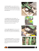
INSTALLATION 1. Tractor Preparation: Before attempting to install the Outback® Hitch, park the tractor on a smooth level floor with adequate clearance to work around the drawbar area. Remove any accessories installed on the tractor drawbar including the hammerstrap clevis and safety chain holder. If the tractor is equipped with a drop-style drawbar, remove the drawbar and flip it upside down. Reinstall the drawbar as shown. The Outback® Hitch requires a minimum mounting clearance of 14-1/4 in.
3. Mounting the Hitch: Using a forklift, floor jack, or chain hoist, position the Outback® Hitch under the tractor drawbar as shown. Notice that the hydraulic hoses to the left cylinder must route over the top of the tractor drawbar. Center the hitch directly under the tractor drawbar with the drawpin hole lined up over the center of the corresponding hitch mounting hole. E 4.
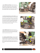
7. Move Hitch Drawbar Right: Start the tractor and enable the hitch hydraulic remote outlet. The coils on the hitch hydraulic control block have manual push button overrides. Using a small screwdriver or common nail, push the manual override at the center of the rear coil to move the hitch drawbar to the far right extent. Disable the hitch hydraulic remote outlet, and shut off the tractor. 8.
. Determine Tilt Sensor Location: The tilt sensor should be mounted directly onto the rear tractor frame in an area protected from mud and flying debris. The sensor must be oriented relative to the forward travel direction as shown on the sensor decal. Orient the sensor with the label up and the connector towards the rear. The sensor may require re-orientation onto the sensor bracket to accommodate mounting directly to the tractor frame. 12.
14. Exchange Power Cable: Install the Outback® S, using the instruction booklet provided. Do not use the power cable provided with it. Locate the Power/CAN cable in the Hitch package. It has two connectors and a cigarette lighter plug. Install the connector with two cables coming out into the S Power/CAN port as shown. Twist the connector firmly until it locks into place. Note: The Outback® Hitch may also be used in combination with the optional Outback® 360.
18. Install CAN Cable: Install the remaining Power/CAN connector (from either Step 14 or 15) into the upper CAN port on the Hitch console as shown. Twist connector firmly until it locks into place. For permanent installations, we recommend removal of the cigarette lighter plug and hard wiring the leads to a reliable 12-volt power supply. The red wire goes to positive and the black wire to negative. Note: Cigarette lighter sockets are notorious for intermittent power.
GET ACQUAINTED WITH THE CONTROLS LEFT/RIGHT ARROWS MODE RUN/HOLD CENTER S PRESENT INDICATOR HITCH POSITION INDICATORS HITCH POSITION INDICATORS: A series of 21 lights indicate the current hitch pin position relative to the center of the tractor. Each light represents approximately one inch of hitch pin offset. S PRESENT INDICATOR: This light indicates the presence of the Outback® S along with its GPS operational status. If the light is off, communication with the S cannot be established.
POWER UP SETUP 1. Power up both units: Turn on the power switches of the S and Hitch in any order. The S will boot up and begin acquiring a DPGS signal. The Hitch will establish communication with the S and wait for the DPGS signal to be acquired. Configuration of the Outback® Hitch is accomplished through the S, or 360, menu system. During power-up, the Hitch is detected, and an additional menu option is included to configure the Hitch for operation. To access the menu: Press the MENU button.
OPERATION The operation of the Outback® Hitch is quite simple. Turn it on, activate the tractor hydraulics, select the desired MODE, press RUN, and the rest is automatic. Note: As a safety feature, the tractor must be traveling faster than one mile per hour before the RUN button can enable active hitch control. Manual Mode: This mode allows the operator to position the hitch pin at any desired offset using the LEFT/RIGHT ARROWS.
MAINTENANCE Proper maintenance of the Outback® Hitch mechanical components will ensure years of dependable service and protect your investment. GREASE LOCATIONS Initial Installation: After the first few hours of operation, check the tightness of all Hitch mounting bolts and hardware. Substantial wear will occur to the Hitch and tractor drawbar if mounting bolts are not properly tensioned.
CONTACTING THE FACTORY Outback Guidance® Division of RHS, Inc. 2005 West Oregon Street, Box 394 Hiawatha, KS 66434 USA All correspondence to the factory must be in English. ONLINE: http://www.outbackguidance.com PHONE: Monday Through Friday 8 A.M. - 5 P.M. U.S. Central Time U.
Limited Outback® Hitch One-Year Warranty RHS, Inc. ("RHS") manufactures its hardware products from parts and components that are in accordance with industry standard practices. RHS warrants that the hardware products it manufactures will be free from defects in materials and workmanship. The limited warranty term is one year, beginning on the date of invoice to the original purchaser. Damage caused by shipping the product(s) to the original purchaser is covered under this limited warranty.
Limited Outback® Hitch Three-Year Extended Service Plan The Outback® Hitch ESP only applies to the electronic components of the product. Including the console, console mounting, tilt sensor and related cables. The term “hardware” below applies only to the non-software portions of the electronic components. Coverage for the mechanical portions of Outback® Hitch are described in the one-year warranty statement. RHS,Inc.
PARTS LISTING Outback-Hitch Drawbar Guidance System REF. 1 2 3 4 5 6 7 8 9 10 11 12 P/N OBK-S OBK-360 60081 60099 60098 AB674 TS-7R DOM-OBK03 ® GP S IM PLE M EN T G U I DA NC E DESCRIPTION QTY.
Console Mounting Details REF. 1 2 3 4 5 6 7 8 P/N 60066 60063 AB440 60065 60064 AB441 60097 60068 DESCRIPTION Vacuum Cup, 4-1/2" /w 1/4NC Insert Washer, Rubber - 2-1/4OD x 3/8ID x 1/8T Base, Console Mounting - OBK-S/360 Knob, 3-Arm - 1/4NC x 1/2 Stud, 1-1/8 Dia. Washer, Rubber - 1-1/2OD x 3/4ID x 3/32T Frame, Console Mounting - OBK-S Outback Hitch Console Knob, Thumbscrew - #8-32 x 1/4" Stud QTY. 1 1 1 3 2 1 1 2 Tilt Sensor Mounting Details REF. 1 2 3 4 P/N AB673 AB677 B#8.
Hydraulic & Electrical Assembly REF. 1 2 3 4 5 6 7 8 9 10 11 12 13 14 15 P/N 60229 FW38N B38.4 60233 60232 60231 69266 8FP-QM AB674 WA027 B14.34 60257 DEC-HAZ01 DEC-MT4163 ® GP S IM PLE M EN T G U I DA NC E DESCRIPTION QTY. Mechanical Assy, see page A4 Hydraulic Valve Assy, see page A6 1 Washer, Narrow Flat - 3/4"OD x 13/32ID x 1/16"thk, ZP 2 Bolt, 3/8NC x 4 Gr5 ZP 2 Hose, Hyd. - 1/4"x24"lg, #4 Female JIC x #4 Male JIC 2 Hose, Hyd. - 1/4"x18"lg, #4 Female JIC x #4 Male JIC 2 Hose, Hyd.
Mechanical Assembly REF. 1 2 3 4 5 6 7 8 9 10 11 12 13 14 15 16 P/N AB663 60214 B12.212 LN12 B34.6 60220 60217 60216 60218 60219 CLP34.2 60220 CP532.114 AB664 N34 DESCRIPTION Wment, Hitch Bottom Pin, Hitch Main Bolt, 1/2NC x 2-1/2 Gr5 ZP Nut, Lock - 1/2NC ZP Bolt, 3/4NC x 6 Gr5 ZP Washer, Shim - 1-1/8"OD x 3/4"ID x 0.062"TH Washer, Shim - 1-5/8"OD x 1-1/8"ID x 0.
Drawbar Sub-Assembly REF. 1 2 3 4 5 6 7 8 9 10 11 P/N AB665 LSI-2022-20 60245 69573 AB667 B56.1FSC AB676 BM20.110 LWM20 NM20 60205 ® GP S IM PLE M EN T G U I DA NC E DESCRIPTION Wment, Hitch Drawbar Sleeve, L280 - 1.25"ID x 1.375"OD x 1.25"Lg Bearing, Composite Sleeve - 3/4"ID x 7/8"OD x 3/4"Lg Zerk, Grease 1/4-28 Threaded Wear Plate, Hitch Drawbar Bolt, Hex Socket Flat Head - 5/16NC x 1", ZP Flat, Safety Chain Support Bolt, Hex - 20m2.5 x 110, YZ Washer, Lock - M20, YZ Nut, Hex - 20m2.
Hydraulic Component Details REF. 1 2 3 4 5 6 7 8 9 10 11 P/N 60239 60240 4MB-4MJ90 60241 69573 60234 60235 60236 60237 60238 4MB-4FJ90 4MB-4MJ90 DESCRIPTION QTY. Replacement Seal Kit /w Instructions 2 Replacement Sensor Kit /w Instructions 1 Adapter, Hyd.
Mounting Hardware Details REF. 1 2 3 4 5 6A 6B 6C 7A 7B 7C 8 P/N B34.4 B34.6 N34 LW34 AB672 AB671 AB669 AB670 60223 60222 60224 60221 ® GP S IM PLE M EN T G U I DA NC E DESCRIPTION QTY.
Clevis Hitch Attachment [Optional] REF. 1 2 3 *4 *5 *6 P/N 60246 60248 60247 BM20.110 LWM20 AB676 DIP-OB014 DESCRIPTION Hammerstrap, Cat. 3 Drawbar Hitch Pin Trigger, Cat 3 Drawbar Hitch Pin, Cat 3 Drawbar Bolt, Hex - 20m2.5 x 110, YZ Washer, Lock - M20, YZ Flat, Safety Chain Support Installation Instructions, Clevis Hitch Attachment QTY. 1 1 1 2 2 1 1 *Items 4, 5, & 6 supplied with drawbar hitch assembly.
® GP S IM PLE M EN T G U I DA NC E A9
A10 ® GP S IM PLE M EN T G U I DA NC E