HUB Communications Manager User’s Manual
About OutBack Power Systems OutBack Power Systems is a leader in advanced energy conversion technology. Our products include true sine wave inverter/chargers, maximum power point charge controllers, system communication components, as well as breaker panels, breakers, accessories, and assembled systems. Notice of Copyright OutBack HUB Communications Manager User’s Guide © 2008 All rights reserved.
Warranty Introduction Dear OutBack Customer, Thank you for your purchase of OutBack products. We make every effort to assure our power conversion products will give you long and reliable service for your renewable energy system. As with any manufactured device, repairs might be needed due to damage, inappropriate use, or unintentional defect. Please note the following guidelines regarding warranty service of OutBack products: • Any and all warranty repairs must conform to the terms of the warranty.
EU Declaration of Conformity In accordance with EN 45014:1998 We ........................................................... OutBack Power Systems Of ............................................................. 19009 62nd Ave NE Arlington, WA 98223 USA Declare that: Model name/number ................. MATE, MATE2, MATE_B, HUB4, HUB10 Has been designed and manufactured to the following specifications: 73/23/EEC...........................................
OUTBACK HUB Communications Manager INSTALLATION GUIDELINES AND SAFETY INSTRUCTIONS SAVE THESE INSTRUCTIONS Read all instructions, cautionary markings, and all appropriate sections of this installation and user manual as well as other component manuals before using the system. Be cautious around electricity, electrical components, and batteries. Shocks, burns, injury, and even death can occur if an installer comes in contact with electricity.
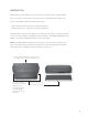
INTRODUCTION OutBack Power Systems’ HUB System Communications Manager allows multiple OutBack devices to connect and integrate at one point via CAT5e cable WITH RJ45 modular jacks. There are two HUB Communication Manager products: • HUB 4, which has four component ports plus a MATE port • HUB 10, which has ten component ports plus a MATE port When the MATE is attached to the HUB 4, it can display and manage any combination of four FX Series Inverters/Chargers and OutBack Charge Controllers.
HUB 10 and HUB 4 Parts Each HUB comes with sufficient fasteners, cables and bushings for most common installations. Please see the enclosed hardware kit for specific parts. Accessories OBCATV-3 OBCATV-6 OBCATV-10 OBCATV-50 Three-foot CAT5e cable with green jacket Six-foot CAT5e cable with green jacket Ten-foot CAT5e cable with green jacket Fifty-foot CAT5e cable with green jacket Mounting The OutBack HUB can be wall-mounted in any orientation.
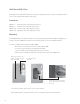
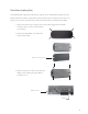
Connecting to the HUB The Master FX plugs into Port 1 HUB Ports (HUB 10) 10 9 8 7 6 5 4 3 2 1 2nd MATE Port is not used 2nd MATE 1st MATE • With the HUB mounted, plug in the FX Inverter/Chargers starting with Port 1. • Port 1’s FX is the Master FX in a multiple FX system. • When all the FXs are connected to the HUB, connect the Charge Controllers in any order. • After all devices are connected to the HUB, the MATE is always plugged in last using the 1st MATE port.
Common Wiring Configurations Single FX Series Inverter/Charger and OutBack Controller • Plug the FX into Port 1 of the HUB. • The Charge Controller and any future OutBack devices can be plugged into any remaining non-MATE ports. Multiple OutBack Charge Controllers Only • Plug one Charge Controller into Port 1 and the others into any remaining ports. • A FLEXnet DC can be plugged into a remaining port as well.
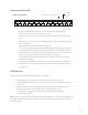
Three-Phase Stacking Only The OutBack HUB is shipped from the factory setup for series (120/240 VAC split phase) and/or parallel (120 VAC or 230 VAC single phase) stacking. If three-phase stacking is desired, the cover must be removed and a jumper position changed. For three-phase stacking using a HUB 4: 1. Remove the black snap on wiring cover and all cables plugged into the HUB. Label the cables to avoid confusion when reconnecting. 2. Remove the four Phillips screws from the bottom of the HUB.
Series/Parallel location Three-Phase location 4. Move the plug-in jumper from the series/parallel location to the three-phase location. 5. Replace the PCB and bottom cover, the snap on wiring cover, and all CAT5e cables.. For three-phase stacking using a HUB 10, follow the same disassembly and assembly instructions as for a HUB 4, but note that the jumper is in a different location as shown below.
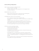
Sample Network Configuration HUB 10 fastened to side of FLEXware 1000 AC Enclosure FLEXware 1000 System OutBack HUB 10 connected to four FX Series Inverter/Chargers and four Charge Controllers MATE Power Up As soon as the MATE cable is plugged into a powered OutBack product, the MATE itself will power-up and display several information screens. G’day Mate (C) 2008 OutBack Power Systems First Screen Second Screen Third Screen Version Code 4.0.5 OxBF5B Serial #: 00000000 Screen EE 4.2.
Searching for Devices HUB FOUND Port Assignment 1> FX 2> MX 5> 6> 9> 10> Silent inv chg 0.0 kw 0.0kw DOWN MATE has found the HUB 3> 7> 2M> Port Assignment screen follows the “HUB Found” screen, each Port showing the product connected to it 4> 8> While navigating the various screens and menus in the MATE, the information displayed often only applies to a single device on a single Port. In these cases, the Port number is displayed in the upper right hand corner of the MATE screen.
Troubleshooting Problem Action HUB power LED does not light The HUB is powered from OutBack Power FXs or Charge Controllers. Be sure all DC breakers for HUB-connected devices are on. Check or replace connecting CAT5e cables if needed. MATE does not find the hub Check the MATE code version is 2.0 or higher. Check and if necessary replace CAT5e cables connecting any device to the HUB.
TWO YEAR LIMITED WARRANTY INFORMATION Hub Communications Manager Products OutBack Power Systems, Inc. (“OutBack”) provides a two year (2) limited warranty (“Warranty”) against defects in materials and workmanship for its Hub Communications Manager Products (“Product(s)”) if installed in fixed location applications. The term of this Warranty begins on the Product(s) date of manufacture or the initial purchase date as indicated on the warranty registration card submitted to OutBack, whichever is greater.
To request warranty service, you must contact OutBack Technical Services at (360) 435-6030 or support@outbackpower.com within the effective warranty period. OutBack Technical Support will attempt to troubleshoot the product and validate that the failure is product related. If warranty service is required, OutBack will issue a Return Material Authorization (RMA) number. A request for an RMA number requires all of the following information: 1.
HUB Communcations Manager Limited Warranty Registration Complete this form and return it to: Outback Power Systems Inc. 19009 62nd Ave. NE Arlington, WA 98223 NOTE: Please submit a copy (not the original) of the Product purchase invoice, which confirms the date and location of purchase, the price paid, and the Product Model and Serial Number.
17
Corporate Office 19009 62nd Avenue NE Arlington, WA USA (+1) 360-435-6030 www.outbackpower.com European Sales Office C/ Castelló, 17 08830 - Sant Boi de Llobregat BARCELONA, España Phone: +34.93.654.