
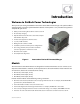
- Outback Power Systems, Inc. Battery Charger User Manual


Installation
18 900-0111-01-00 Rev A
Grounding
WARNING: Shock Hazard
The unit must be connected to a grounded, permanent wiring system. If a bond is made
between neutral and ground make sure only one bond is present in the AC system at any
time. Some codes require the bond to be made at the main panel only.
WARNING: Shock Hazard
For all installations, the negative battery conductor should be bonded to the grounding
system at only one point. If the OutBack GFDI is present, it can provide the bond.
IMPORTANT:
OutBack products are not designed for use in a positive-grounded system. If it is necessary
to build a positive-ground system with OutBack products, contact OutBack Technical
Support at
360.618.4363
before proceeding. Additionally, consult the online forum at
www.outbackpower.com/forum/
, where this subject has been discussed extensively.
Table 3 Ground Conductor Size and Torque Requirements
Terminal Location Minimum Conductor Size Torque Requirements
Center AC Terminals
6 mm (#10 AWG or 0.008 in) 2.8 Nm (25 in-lbs)
DC Box Lug
16 mm (#6 AWG or 0.021 in) 5.1 Nm (45 in-lbs)
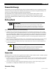
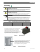
Figure 6 DC Ground Lug
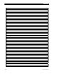
Figure 7 AC Ground Terminals
The inverter’s DC ground is a box lug located next to
the negative DC battery terminal. Local codes or
regulations may require the DC ground to be run
separately from the AC ground. Also, if present, it will
be necessary to remove the DC Cover before making
the ground connection. (See the next page.)
The two Chassis Ground/PE terminals are electrically
common. Only one terminal can be used if
connecting to an external ground bus. The other
terminal may be used if connecting to a device with
its own ground wire, such as a generator.