
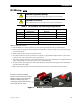
- Outback Power Systems, Inc. Battery Charger User Manual


Installation
900-0111-01-00 Rev A 23
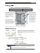
AUX Wiring
The AUX+ and AUX– terminals are a switched 12 Vdc supply. The AUX can respond to many criteria
and control many functions. These include cooling fans, vent fans, load diversion, fault alarms, and
automatic generator control. The AUX output can also be controlled externally through the system
display. (For generator control, see the next page. For all other functions, see the system display
manual and the International Series GFX Operator’s Manual.) The AUX can only control one function at
a time.
The terminals can supply up to 0.7 amps at 12 Vdc (8.4 watts). This is sufficient to drive a small fan, or a
relay which can control a larger device. The terminals accept up to 2.5 mm (#14 AWG) wire.
The AUX circuit contains electronic overcurrent protection, which resets after being overloaded. No
additional fuses are required for the AUX terminals.
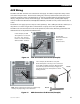
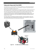
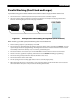
Figure 14 AUX Connections for Vent Fan (Example)
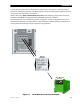
Figure 15 AUX Connections for Diversion (Example)
In this example, the AUX
directly drives a 12-volt vent
fan. The + and – wires on
the fan are connected to the
AUX+ and AUX– terminals.
Fan
T
he AUX LED
illuminates when the
AUX output
becomes active.
In this example, the AUX drives a relay that
diverts wind power. The relay’s coil is connected
to the AUX+ and AUX– terminals. When the AUX
closes the relay (based on battery voltage), the
relay diverts the excess wind power to a water
heating element.
Relay
Element
Turbine
Note: Relays and elements shown are examples only
and may vary depending on the installation.