
- OutBack Power Systems FX and VFX Inverter/Charger Installation and Programming Manual


Copyright 2003 OutBack Power Systems, Inc. FX & VFX “E” Series Inverter/Charger System Installation & Programming Manual
19009 62
nd
Ave NE, Arlington WA 98223 USA 900-0027-2
Tel 360 435 6030 Fax 360 435 6019
Rev 7.1 06/08/06 Page 51
MATE SCREENS
AUXILIARY MENU
The AUX (auxiliary) section can be used to control external AC or DC loads, signal a generator start system, send a fault alarm signal,
or to run a fan. The AUX output provides a 12 vdc, 0.7 adc output on the AUX terminals located in the AC wiring compartment.
ADV/FX/PAGE1--------
choose category:
ADV INV CHGR PG2
↓
ADV/FX/PAGE2--------
choose category:
PG1 GRID GEN PG3
↓
ADV/FX/PAGE3--------
choose category:
PG2 AUX STACK PG4
↓
ADV/FX/AUX-------P00
aux output AUTO
control
DOWN INC DEC PORT
↓
ADV/FX/AUX-------P00
aux output AC Drop
function
DOWN INC DEC PORT
↓
ADV/FX/AUX-------P00
aux output DivertAC
function
DOWN INC DEC PORT
↓
ADV/FX/AUX-------P00
aux output DivertDC
function
DOWN INC DEC PORT
↓
ADV/FX/AUX-------P00
aux output Cool Fan
function
DOWN INC DEC PORT
↓
ADV/FX/AUX-------P00
aux output Vent Fan
function
DOWN INC DEC PORT
↓
ADV/FX/AUX-------P00
aux output Fault
function
DOWN INC DEC PORT
↓
ADV/FX/AUX-------P00
aux output GenAlert
function
DOWN INC DEC PORT
↓
ADV/FX/AUX-------P00
aux output LoadShed
function
DOWN INC DEC PORT
↓
ADV/FX/AUX-------P00
aux output Remote
function
DOWN INC DEC PORT
↓
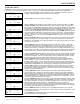
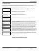
Once the password has been correctly entered, the ADV - CHOOSE CATEGORY: screen is
displayed. Selecting
<PG2> shows a second screen of categories.
Selecting
<PG3> shows a third screen of categories.
Selecting
<AUX> allows adjustment of the auxiliary output set points and operation. The AUX
OUTPUT CONTROL screen allows selection of the mode of the AUX output. Selecting INC or
DEC changes the mode between OFF, AUTO, and ON. Selecting OFF disables the AUX output
from operating. Selecting AUTO allows the AUX output to automatically perform the function that
is selected in the
AUX OUTPUT FUNCTION screens below. Selecting ON forces the AUX
output to be kept ON regardless of the function selected. Pressing
<DOWN> allows the selection
of the AUX OUTPUT FUNCTION. There are nine functions in this section. The default setting is
“Cool Fan” which is set to run a Turbo Kit without any programming. The function at the top of
the menu is “AC Drop”. The user must press
<INC> three times in order to get to the top of the
list of functions.
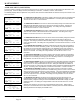
Selecting
AC DROP enables the AUX output when an AC source is connected to the FX. When
the AC source ceases (due to a power outage, or a generator quitting) the Aux output will be
deactivated. This allows the user to attach an indicator to the AUX output to show the user when
an AC source is connected.
Selecting
DIVERT enables the AUX output to function as a diversion controller. This can be
used to send excess power from a renewable energy source to a load. This can allow control of
sources such as wind turbines or hydro-generators. Two choices of DIVERT are provided –
‘DivertDC’ and ‘DivertAC’. ‘DivertDC’ is used to divert power to DC loads and ‘DivertAC’ is used
to divert power to AC loads. The only difference is that the ‘DivertAC’ setting will turn off the AUX
output if the inverter is overloaded. See the next page to adjust the set points for this function.
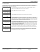
Selecting
COOLFAN (default) enables the AUX output to function as a thermostatically operated
ventilation system controller. When the FX approaches an over temperature condition, the AUX
output will be energized. This can be used to power a small 12 vdc brushless “muffin” type fan,
the Turbo Kit, or can be used to control a larger cooling fan via a 12 vdc coil relay.
Selecting
VENTFAN enables the AUX output to function as an automatic battery ventilation
system controller. The AUX output can provide 0.7 amps of power for connection to a 12 vdc
brushless “muffin” type fan. The fan will be automatically turned on when the voltage exceeds
the VENTFAN ON voltage set point. The fan can be set to operate intermittently by adjusting the
VENTFAN OFF TIME PERIOD. See the next page to adjust the set points for this function.
Selecting
FAULT enables the AUX output to function as an alarm output. When the FX enters
any of the error conditions, the AUX output is energized. This can be used to send an alarm
signal via radio, pager or telephone dialer. It also can be used to log error conditions by using it
to trigger an event recording device.
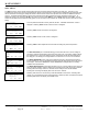
Selecting
GENALERT enables the AUX output to function as a simple voltage controlled
generator start signal. ‘GenAlert’ can be used to “alert” the system user to start the generator
due to the battery voltage being low. Only connection to a 2-wire type generator is possible and
must be done through a 12 volt DC relay. Time delays for ON and OFF are adjustable. Using
‘Advanced Generator Start’ (AGS) will override any AUX function that is programmed. See the
next page to adjust the set points for this function.
Selecting
LOADSHED enables the AUX output to function as a load management system. When
the battery voltage drops below the LOAD DISCONNECT set point for more than 3 seconds, the
AUX output is energized. Connecting a normally closed (NC) relay to the circuitry of non-vital
loads will disengage them with this function. LOADSHED will also occur when the FX
approaches an over-temperature condition or when the AC output voltage drops below 202 vac
for more than 3 seconds. There is a 3-minute fixed delay before the AUX output is de-energized.
See the next page to adjust the set points for this function.
Selecting
REMOTE enables the AUX output to be controlled by the MATE or a PC computer
connected to the MATE PC communication port. This function is currently not operational. It will
be operational in the future.
Press
<DOWN> after selecting the AUX OUTPUT FUNCTION of your choice. The AUX menu
section is continued on the following page.