
OutBack Power Programming Guide

Page 36
900-0125-12-01 Rev A
©2017 OutBack Power Technologies. All Rights Reserved.
Page 37
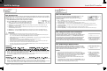
M-4. Grid Use Time
EXAMPLE #1:
Monday – Friday evenings at 6 PM, the MATE3s issues a USE command to the inverter allowing the AC input source to be used.
Monday – Friday mornings at 6 AM, a DROP command is issued.
On Friday evening at 6 PM, a USE command is issued but since the weekend Start and Stop times are equal, the weekend use
time is disabled. No DROP command will be issued until Monday morning at 6 AM.
EXAMPLE #2:
Monday – Thursday evenings at 6:00 PM, the MATE3s issues a USE command to the inverter allowing the AC input source to be used.
Monday – Friday at 6:00 AM, a DROP command is issued. On Friday evening at 6:00 PM, a USE command is issued.
Saturday morning a DROP command is issued at 8:00 AM. Saturday afternoon at 4:00 PM, the inverter will USE again until Sunday
morning at 8:00 AM. Sunday evening at 4:00 PM., a USE time period will start, ending on Monday morning at 6:00 AM.
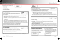
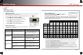
Enable — either enables (Y) or disables (N) the Grid Use Time function.
Three Enable fields are present for the three possible weekday usages.
Weekday: Use — the daily time (00:00 to 23:59, Monday through Friday) when the system is told to Use the utility grid.
Three different Use times can be set.
Weekday: Drop — the daily time (00:00 to 23:59, Monday through Friday) when the system is told to Drop the utility grid.
Three different Drop times can be set.
Weekend: Use — the daily time (00:00 to 23:59, Saturday and Sunday) when the system is told to Use the utility grid.
Weekend: Drop — the daily time (00:00 to 23:59, Saturday and Sunday) when the system is told to Drop the utility grid.
This function allows the system to connect to (use) the utility grid and disconnect from (drop) it on a schedule.
Grid Use Time mode is programmed separately for weekday and weekend connect times. Before turning the
Grid Use Time mode on, set all weekday and weekend time periods.
o Three Grid Use Time periods may be programmed on weekdays.
o Only one Grid Use Time may be programmed on a weekend.
IMPORTANT:
The time and date must be accurately programmed for this mode to function properly.
Care must be taken when programming weekday and weekend times that encompass USE periods past midnight (12:00
a.m.). The user must take into account weekday USE periods that will end on a Saturday.
Grid Use Time cannot be used with HBX mode or Load Grid Transfer. These functions have incompatible priorities and
will conflict with each other.
Grid Use Time cannot be used if the inverter’s Mini Grid AC input mode is used (see page 11).
These functions have incompatible priorities and will conflict with each other.
The MATE3s does not automatically adjust its clock for Daylight Savings Time. This may affect timing of grid usage.
If a start time equals a stop time, no action will be taken and the time period is ignored.
If the battery voltage falls below the inverter’s Low Battery Cut-Out voltage, the inverter will automatically connect to the
AC input source regardless of the time-of-day setting.
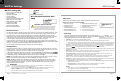
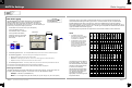
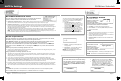
M-5. Load Grid Transfer
The MATE3s can force all inverters to automatically reconnect to the
utility grid, even if the normal mode is to be disconnected.
Inverters can reconnect based on high output loads, or based on
low battery voltage.
Mode — Enabled allows automatic grid reconnection. Disabled means reconnection will only occur according to the
inverter’s own operating mode or other programming.
AC Load Threshold — The amount of load which requires the inverter to connect.
Load Connect Delay — The length of time the AC Load Threshold must be exceeded before the inverter connects.
Load Disconnect Delay — The length of time the loads must remain below the AC Load Threshold before the inverter
disconnects from the grid.
Connect Low Battery — The low battery voltage level which requires the inverter to connect.
Disconnect High Battery — The voltage which the batteries must reach before the inverter disconnects from the grid.
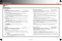
M-6. Charge Controller Float Coordination
This menu enables the coordination of more than one OutBack
FLEXmax charge controller. (This function also works on MX60 charge
controllers with firmware revision 5.11). This enables the devices to
enter the float stage, or perform other activities, simultaneously rather
than individually. Float Coordination means that when one charge
controller finishes a bulk charge and moves into the float stage, the
MATE3s directs any other charge controllers into the float stage as well.
Enable — either enables (Y) or
disables (N) the Charge Controller
Float Coordination function.
M-7. Global Charger Output Control
The global charger control allows the MATE3s to limit the DC current
delivered by all FLEXmax charge controllers in the system. This menu
specifies a maximum allowed charging current for the system. The total
charge controller current cannot exceed this number.
NOTES:
This function cannot limit charge current from inverters of any kind.
However, inverter current is counted in the total. For example, if Maximum
Battery Charge is set to 200 Adc and the inverters charge at 125 Adc, the
charge controller current cannot exceed the difference, which is 75 Adc.
The controller current will be limited as necessary.
This function requires the system to have a FLEXnet DC battery monitor
installed in the system.
The FLEXmax charge controllers must be set to Grid-Tie Mode in order to
establish priority for this function. (See page 19.) However, the inverters in
the system cannot use grid-interactive functions (if any).
Enable — either enables (Y) or
disables (N) the Global Charger
Output Control function.
Maximum Battery Charge –
the maximum combined charging
current (10 to 800 amps) allowed.
Load Grid TransferMATE3s Settings