
OutBack Power Programming Guide
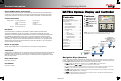

Inverter Settings (I)
Many of the inverter settings in this section apply to all classes of inverters. However, some inverters use different
screens. In cases where screens are different or product-specific, the title indicates the inverter class.
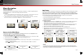
I-2. AC Input and Current Limit
This menu controls the input current that the inverter can draw. It has
independent settings for two AC sources. It is common for one source to be
the utility grid and the other is an AC generator. The settings are labeled
accordingly. (It also has an independent setting for the inverter’s charger.)
NOTE: FX-class, FXR-class, and Radian-class inverters interact differently with
multiple AC sources. Note also that several items in this menu are also controlled
in the <Input Select> soft key menu. See the MATE3s Overview Guide.
Adjust these settings to the size of the input circuit breaker or conductor.
This is for protection. If combined charging and loads exceed this setting,
the inverter automatically reduces its charge rate. (The loads receive
priority.) If the loads exceed the limit on their own, the charge reduces to
zero. This setting may be assisted by the Input Support
function, if present.
Beyond this point, the input breaker may trip. This is accompanied by a
MATE3s event and the warning Input Amps > Max.
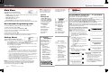
I-1. Search
This function can minimize inverter power draw when no loads are present.
Name — Adjusts the Search mode sensitivity while searching for loads.
Setting this item to zero will disable Search mode.
Pulse Length — Adjusts the duration of search pulses (in single AC cycles).
Longer pulses will detect loads more quickly. This consumes more power.
Input Type — (FX-class and FXR-class only; A, C, D) – The inverter has two choices for AC sources: Grid or Gen. It cannot use both
at once, but it can be switched between them using an external selector switch. The user can select between defined parameters for
each source. (See I-3. See page 42 for the effects of the Profile Wizard on this setting.)
In FX-class grid-interactive models, this sets the charging format and other parameters. Gen prevents the inverter from selling power.
Input Priority — (Radian-class only; B) – The inverter can be wired to two AC sources: Grid or Gen. It can accept either source but
cannot use both at once. However, it will accept one input as a default selection if both sources are active at the same time.
Grid and Gen Input AC Limit — Adjusts the inverter’s draw to the size of the appropriate input circuit or source. (See page 42.)
Charger AC Limit — Adjusts the draw of the inverter’s charger. This setting can be limited to avoid accidentally overcharging the
batteries. It should not exceed the maximum charge rate of the battery bank. (See page 42.)
Charger Control — (FXR-class and Radian-class only; A and B) – Turns off the charger for an individual inverter and prevents it from
responding to global charger commands.
Input Support — (FX-class only; C) – Enables the Input Support function, if present. Not all FX-class inverters have this function (D).
NOTE: Input Support is present in Radian- and FXR-class inverters, but is not selectable. It only works in Support mode. See I-3a.
NOTE: If multiple parallel inverters are installed with a limited AC source, the combined amperage settings must be less
than the AC input circuit. The MATE3s Profile Wizard can perform this calculation. (See page 40.)
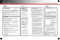
o I-4. AC Output
o I-5. Low Battery
o I-6. Battery Charger
o I-7. Battery Equalize
o I-1. Search
o I-2. AC Input and Current Limit
o I-3a. Grid and Gen AC Input Mode and Limits (FXR/Radian-class)
o I-3b. Grid and Gen AC Input Voltage Limits (FX-class)
Pulse Spacing — Adjusts the time between
search pulses (in single AC cycles).
Shorter spacing will detect loads more
quickly. This consumes more power.
o I-8. Auxiliary Output / Relay
o I-9. Inverter Stacking
o I-10. Power Save Ranking
o I-11. Grid-Tie Sell
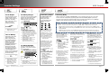
B
A
C
D
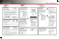
I-3b. Grid and Gen Input Voltage Limits (FX-class only)
The inverter will not connect to an AC source unless specific conditions are
met. When Input Type is set to Grid or Gen in the AC Input and Current
Limit screen (I-2), these menus adjust the limits on acceptable source voltage.
Frequency is not adjustable.
Lower and Upper Voltage Limit — Set the limits on the acceptable AC voltage. If the
source is within the appropriate range, the inverter will accept it. If it exceeds this range,
the inverter will disconnect itself. It will return to inverting if that function is active.
Transfer Delay — Sets the duration that the input AC voltage or frequency may exceed limits before the inverter
disconnects itself. This may be preceded by a warning and may be followed by a Last AC Disconnect message. (See the
MATE3s Overview Guide.)
Connect Delay — Sets the designated delay period before the inverter begins accepting power from the source. This is
intended to give a generator time to stabilize its output. It is not the same as the AGS warmup period (see page 25).
NOTE: Items 1-3a and 1-3b use the same location in the Inverter menu, but are used in different models.
I-3a. Grid and Gen Input Mode and Limits
(FXR-class and Radian-class)
The inverter will not connect to an AC source unless specific conditions are met.
Each input selection has a menu to adjust the conditions. In the Radian, the
Grid Input Mode and Limits menu applies to the input labeled GRID.
Gen Input Mode and Limits affects the GEN input. In FXR inverters,
either menu can apply depending on whether the single input is set to accept
Grid or Gen. See I-2.
When the conditions are met, the inverter will accept the source after the designated delay.
Input Mode — Sets this input to one of seven AC input modes (see list). Each mode has specific advantages
for a particular application. (See page 42 for the effects of the Profile Wizard on this setting.)
Voltage Limit Lower and Upper — Set the acceptable AC voltage. If the source is within this range, the inverter
accepts it. If it exceeds this range, the inverter disconnects itself. It will return to inverting if that function is active.
Transfer Delay — Sets the duration that the input AC voltage or frequency may exceed limits before disconnection.
This may be preceded by a warning and may be followed by a Last AC Disconnect message.
(See the MATE3s Overview Guide.)
Connect Delay — Sets the designated delay period before the inverter begins accepting power from the source.
This is intended to give a generator time to stabilize its output. It is not the same as the AGS warmup period (see page 25).
GridZero Mode
DoD Volts — Adjusts the lowest allowable battery discharge voltage. Loads will switch to grid power when this setting is reached.
DoD Amps — Adjusts the maximum current (in AC amperes) at which GridZero mode draws power from the batteries.
Mini Grid Mode
Connect to Grid — Adjusts the battery voltage setting that causes the inverter to reconnect to the utility grid in Mini Grid mode.
(Connect) Delay — Adjusts the delay period after reaching Connect to Grid before the inverter reconnects to the grid.
AC Input
Modes
o I-12. Module Control
o I-13. Calibrate
o I-14. Grid Interface Protection
o I-15. Model Select
NOTE: See the inverter literature
for more information on any setting.
o I-16. Reset to
Factory Defaults
Page 10
900-0125-12-01 Rev A
©2017 OutBack Power Technologies. All Rights Reserved.
Page 11
Grid and Gen AC InputSystem Settings