
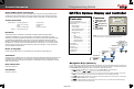
OutBack Power Programming Guide
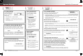
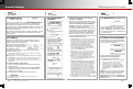

I-9. Inverter Stacking
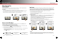
This menu contains settings to coordinate, or “stack”, multiple inverters. Stacking assigns an inverter to a
particular phase or output. Any inverter connected to an OutBack HUB product must be designated as master
or slave of some type. Stacking configurations and other details are discussed in the inverter literature.
The Change soft key enters a new series of screens. The inverter’s output is disabled as shown below.
This prevents phase shifting and other problems which can arise from inverters remaining active while their
programming is changed.
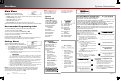
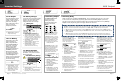
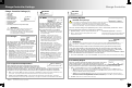
I-10. Power Save
Ranking
Each inverter uses power
while it remains on, even if it
is not inverting or charging.
Power Save can put slave
inverters into Silent mode.
This mode minimizes the idle
consumption. The inverters
will come on again when the
loads require power.
!
CAUTION: Equipment Damage
Ensure the inverter outputs are turned off, or disconnected, before programming.
Failure to do so could result in damage to the equipment.
IMPORTANT:
All inverters connected to ports on the HUB Communications Manager must be
assigned valid designations for stacking and Power Save Levels. If this is not
done, the system may give any number of error messages or other symptoms.
All stacked inverters must have the same firmware revision. If inverters are
stacked with different firmware revisions, any inverter with a revision different from
the master will not invert and will not connect to an AC source. The MATE3s will
register an event and will display the following message:
An inverter firmware mismatch has been detected. Inverters X, Y, Z
1
are disabled.
Visit www.outbackpower.com for current inverter firmware.
Combining unstacked or incorrectly stacked inverters may cause similar problems.
If more than one model series is stacked together, any inverter model belonging to
a series different from the master will not invert and will not connect to an AC
source. The MATE3s will register an event and will display the following message:
A model mismatch has been detected. Inverters are incompatible. Inverters X, Y,
Z
1
are disabled. Match all models before proceeding.
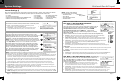
Stack modes are inverter-dependent. The list to the right shows all possible
modes. Some are not available with all OutBack inverters.
The output is activated when the selection is complete. Regardless,
make certain to observe the caution below when programming.
Stack Mode — Assigns the inverter to a specific priority and
output (phase). This assignment must be made for every
inverter that is connected to a HUB port. In a multiple-inverter
system, one inverter must be assigned as master. The others
are assigned to other phases or as slaves.
Master or 1-2phase Master — The primary inverter for
single-inverter systems, single-phase stacked systems, or
split-phase systems. In models where this selection reads
Master, it is also used for three-phase systems.
Slave — A secondary inverter in a stacked system.
Classic Slave — A secondary (L2) inverter, partly
independent of the master.
OB Slave L1 — A secondary (L1) inverter for single-phase
(parallel) or split-phase multiple-inverter systems.
OB Slave L2 — A secondary (L2) inverter for split-phase
multiple-inverter systems.
L2 Phase Master — The subphase master inverter for the
L2 output in a split-phase system.
B Phase (C Phase) Master — The subphase master
inverters for the B or C outputs in a three-phase system.
3p Master or 3phase Master — The primary inverter for
three-phase systems that include the selection 1-2ph
Master as shown above. The 3p Master is Phase A.
3phase Classic B (C ), or 3p OB Slave A (B/C ) —
A secondary inverter for three-phase systems. Used in
models where the phases are manually assigned.
3phase Slave — A secondary inverter for three-phase
systems. Used in older models for B and C phases where
the phases are assigned based on the HUB port.
See the inverter literature for more information on these
stacking modes.
IMPORTANT:
Inverters with higher-level settings will go
into Silent mode sooner. The master
must stay on and should have the lowest
setting. The default is zero (0). Normally
it should be left at zero (0).
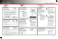
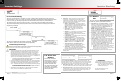
I-11. Grid-Tie
Sell
This menu sets basic limits for Offset operation, which
includes the “grid-tie” (grid-interactive) function.
Offset Enable (also called Grid-Tie Enable*) — Enables or
disables the inverter’s Offset function by selecting Y or N.
This controls grid interaction in applicable models. It also
controls offset operation in the Support, Mini Grid, and
GridZero modes in applicable models.
NOTE: If Enable Auto Grid-Tie Control (see page 38) is
set to Y (yes), Offset Enable may be turned on according to
MATE3s and FLEXnet DC automatic criteria, even if it is
manually turned off here. Offset Enable will switch to Y.
Sell Voltage — Sets the operating point for offset operation,
including the grid-interactive function. When this point is
exceeded (usually from renewable charging), the inverter
sends the extra power to the loads. This offsets the use of the
AC source. If the energy exceeds the loads, a grid-interactive
inverter can sell the power to the utility.
Grid-Tie Window* — Sets the requirements for the utility grid
before the grid-interactive function can work. If the voltage
and frequency are within designated ranges, the inverter
can sell power. Otherwise, this function will not operate.
(A message will appear in the Sell Status screen.) Two
selections are available, IEEE and user. Specific settings for
each set point are listed in the inverter literature.
The IEEE selection has narrower settings than the user setting.
IEEE is required by most utilities in the United States. (For
American models, its voltage and frequency criteria are preset to
the requirements of UL1741 and IEEE 1547.)
*Only used in GS8048 and grid-interactive FX-class inverters
Selecting Power Save Ranking will bring up one of the menus below. This
depends on whether the inverter on that port has been set as a master (including
subphase masters) or a slave. The inverters are given a “rank” or level number.
This controls the order in which slaves activate (or return to Silent mode).
Master Power Save Level — Sets the rank of the master or subphase master.
Any inverter ranked equal or less than the master will not enter Silent mode.
Slave Power Save Level — Sets the ranking of slave inverters. This rank
controls the order in which slaves activate (or return to Silent mode). Lower
rank numbers activate when lesser loads are applied. Higher ranks only
activate when the load increases to a high level.
See the inverter literature for more
information on Power Save.
Page 14
900-0125-12-01 Rev A
©2017 OutBack Power Technologies. All Rights Reserved.
Page 15
Inverter StackingInverter Settings