MX60 PV MPPT (Maximum Power Point Tracking) Charge Controller Installation, Programming and User’s Manual
Warranty Summary Dear OutBack Customer, Thank you for your purchase of OutBack products. We make every effort to assure our power conversion products will give you long and reliable service for your renewable energy system. As with any manufactured device, repairs might be needed due to damage, inappropriate use, or unintentional defect. Please note the following guidelines regarding warranty service of OutBack products: • Any and all warranty repairs must conform to the terms of the warranty.
The OutBack Power Systems MX60 PV MPPT Charge Controller is ETL listed to UL1741 (Inverters, Converters, Controllers, and Interconnection System Equipment for Use with Distributed Energy Resources). It is also in compliance with European Union standards EN 61000-6-1 and EN 61000-6-3 (see page 89). About OutBack Power Systems OutBack Power Systems is a leader in advanced energy conversion technology.
TABLE OF CONTENTS INTRODUCTION ........................................................................................................................................................................................ 6 INSTALLATION GUIDELINES AND SAFETY INSTRUCTIONS ............................................................................................. 7 Standards and Requirements ...........................................................................................................................
(DATA) LOGGING ....................................................................................................................................................................................49 Clearing Total and Daily Stats ...............................................................................................................................................50 LOG2 ....................................................................................................................................
SCOPE The manual provides safety guidelines and installation information for the MX60 PV MPPT Charge Controller. It does not provide information about specific brands of solar panels and supplies limited information on batteries. Contact the supplier or manufacturer of the solar panels or batteries for further information.
OUTBACK MX60 CHARGE CONTROLLER INSTALLATION GUIDELINES AND SAFETY INSTRUCTIONS This product is intended to be installed as part of a permanently grounded electrical system as shown in the system configuration sections of this manual with the following important restrictions: • The negative battery conductor should be bonded to the grounding system at only one point in the system. If a GFP is present, the battery negative and ground are not bonded.
WARNING - WORKING IN THE VICINITY OF A LEAD ACID BATTERY IS DANGEROUS. BATTERIES GENERATE EXPLOSIVE GASES DURING NORMAL OPERATION. Design the battery enclosure to prevent accumulation and concentration of hydrogen gas in “pockets” at the top of the enclosure. Vent the battery compartment from the highest point to the outside. A sloped lid can also be used to direct the flow of hydrogen to the vent opening.
OPEN CIRCUIT VOLTAGE/WIRE AND DISCONNECT SIZING Maximum Open Circuit Voltage (Voc) • Voc is the unloaded voltage generated by the solar array. 141 VDC MX60 suspends operation to protect components 150 VDC max open circuit voltage with the coldest environment (although the MX60 shuts down at 141 VDC, it can absorb up to 150 VDC from the array; anything higher than 150 VDC will damage the MX60) • As every brand of panel is different, be sure to know the manufacturer’s specifications.
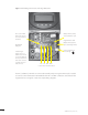
Figure 1 Field Wiring Connections and Surge Protection Use up to 2 AWG wire and torque to 30-inch pounds at terminals. Battery Remote Temp Sensor (RTS) RJ11 jack Programmable AUX Output Jack (supplies up to 200mA @ 12 VDC MATE/HUB RJ45 jack If attaching to plywood, use a 1 5/8” wood screw to secure the MX60 at the top slotted hole and other screws as needed at interior bottom holes.
NOTES • An optional battery Remote Temperature Sensor (RTS) is recommended for accurate battery recharging (only one RTS is needed for multiple OutBack Series Inverter/Chargers and MX60 units when an OutBack HUB and a MATE are parts of the system). When one RTS is used, it must be connected to the component plugged into the Port 1 of the HUB. • AUX modes include powering a relay, LED indicator, and Piezo-buzzer or brushless fan.
Figure 2 MX60 WIRING DIAGRAM WITHOUT A GFP/2, the ground conductors tie into the negative terminal bus bar. 12 OutBack Power Systems Inc.
Figure 3 MX60 WITH GFP/2 WIRING DIAGRAM The GFP/2 requires a separate ground bus bar. OutBack Power Systems Inc.
BATTERY SYSTEM VOLTAGE • The MX60’s default setting is for a 12 VDC battery. • Change the setting after powering up the MX60 if a different battery voltage is used. • The PV array voltage—which must not exceed 150 VDC open circuit—is automatically detected.
POWERING UP The MX60 power-up sequence first activates the unit and brings up a series of screens; some screens allow the user to change the battery voltage. Note: Be sure the PV input and battery breakers are off before starting the power-up sequence. OFF SCREEN (this screen is initially blank at power up) With the PV array and battery breakers off, press and hold soft keys #1 and #3 and then turn on the battery breaker (see Figure 4).
Power-Up Screen Release both soft keys when the OutBack Power OutBack 12V Power Systems Systems screen appears. The selected battery voltage appears in the upper righthand corner. The BATTERY VOLTAGE screen will appear next. MX60 Note: The MX60 designation in the lower left corner will read MX60AU for Australian versions and MX60ES for Spanish versions. BATTERY VOLTAGE 12 24 36 48 60 ^^ EXIT ENTER “^^” indicates the selected battery voltage.
Battery Voltage Screen Press the “ ” soft key to select a battery voltage. The BATTERY VOLTAGE 12 24 36 48 60 ^^ EXIT ENTER MX60’s default values are based on a 12 VDC system. Selecting a higher voltage system will change all the default values (e.g., the values will double with a 24 VDC system, triple with a 36 VDC system, etc.). “^^” indicates the chosen voltage. The MX60 will automatically accept the selected battery voltage if left unattended for 5 minutes in this screen.
STATUS SCREEN The STATUS Screen displays system information. See page 67 for detailed information of the different Operational Modes. The optional OutBack MATE displays MX STATUS screens for convenient distant viewing from the installation location of the MX60. Please see page 71 to view the MX screens displayed on the MATE. The PV voltage will slowly rise to the battery voltage level even when the PV breaker is off – this is normal as the PV capacitor charges up.
PREPARING FOR RECHARGING PV 113 V Bat 12.5 V 00.0 A 00.0 A Watts 0000 Aux Off kWHrs 00.0 Sleeping Turn the PV input breaker on. The MX60 automatically detects the PV input voltage. (Note: If PV voltage registers “000V” when the breaker is on, please check the polarity of the PV wires.) After 5 seconds of stable input voltage, the MX60 PV 087 V Bat 12.5 V 05.0 A 32.9 A Watts 0412 Aux Off kWHrs 00.0 B-MPPT OutBack Power Systems Inc.
ACCESSING THE MAIN MENU The MAIN Menu allows the user to adjust and calibrate the MX60 for maximum performance. From the STATUS screen, press soft key #1 to open the MAIN Menu screen. *Charger Aux Light EQ Misc Advanced Logging Log2 GO EXIT Press the soft key after aligning the asterisk in front of the selected menu choice. Pressing the soft key in the MAIN Menu returns to the STATUS Menu. Press the soft key in your chosen menu to return to the STATUS screen.
CHARGER SETUP This screen allows changes to the MX60’s recharging voltage set points (Current Limit, Absorb, Float): • The presently selected numerical value will have an asterisk “ * ” to the left of it. • Pressing “ ” selects the value to be changed. • You may need to re-enter the password to change these settings. • The default charger output current limit setting is 60 amps and is adjustable up to 70 amps. At 70 amps, a 70A or 80A breaker must be used between the battery and the MX60.
AUX MODE The AUX is a secondary control circuit—essentially, a small power supply that provides a 12 VDC (up to 200 milliamps) output current. It is either active (12 VDC on) or inactive (12 VDC off ). • To access the AUX MODE from the MAIN Menu, press the < >soft key until the asterisk is in front of the Aux selection.
AUX MODE Path *Charger EQ Logging EXIT Aux Misc Light Advance Log2 GO Charger EQ Logging EXIT PASSWORD ***150*** ENTER - Off EXIT + *Aux Misc Light Advance Log2 GO AUX MODE Manual On EXIT NEXT ON OFF AUX MODE Manual NEXT ON OFF • Press the #1 soft key once from the STATUS Menu to open the MAIN Menu. • Press either of the arrow soft keys until the “*” is to the left of “Aux.” • Press the soft key.
AUX modes in order of appearance on the MX60 display: • Manual • Vent Fan • PV Trigger • Float • Error Alarm • Diversion • Low Battery Disconnect • Remote The most commonly used AUX modes: • Vent Fan • Diversion • Low Battery Disconnect When an AUX MODE is ON, 12 VDC is available at the AUX terminals and a condition, such as a voltage set point, is met. Other modes can be programmed in lieu of the specific ones listed here, but the Vent Fan mode is most easily changed (e.g.
Programming the AUX MODES Press the or soft keys to manually AUX MODE Manual On EXIT NEXT ON activate or deactivate AUX MODE. Press the soft key to view the Vent Fan screen. To view other OFF screens, continue to press the soft key. The Vent Fan helps remove hydrogen from the bat- AUX MODE Vent Fan On EXIT NEXT tery room. The ventilation fan referred to here is not the same as the MX60 cooling fan.
Press the soft key to advance to the PV AUX MODE Vent Fan On EXIT NEXT Trigger soft screen. VOLT AUX MODE PV Trigger Off EXIT NEXT TIME VOLT When the PV input is too high and exceeds the user-determined VOLT set point, the AUX MODE PV Trigger activates. Press the soft key to adjust the voltage. Adjust the voltage within a range of 20V - 150V BACK 26 PV VOLTS > 140 by pressing the < - > or < + > soft key.
To adjust the minimum amount of time the PV volt- AUX MODE PV Trigger On EXIT age must remain high before deactivating the AUX MODE, press the
AUX MODE ERROR ALARM On EXIT NEXT The default state of the ERROR ALARM is On, meaning 12 VDC is present at the AUX terminal. If the MX60 has not charged the batteries for 26 hours or more continuously, the inaudible ERROR ALARM goes into an Off state. The ERROR ALARM is intended for remote locations to signal (e.g., a telecommunication signal to a computer) when the MX60 has not recharged for 26 hrs or more. See MISCELLANEOUS Screen 3 Err for a display of the hourly countdown.
Press the
Figure 5 Diversion Load and AUX Wiring Set-Up Illustrated 30 OutBack Power Systems Inc.
Press the soft key to view the Low Batt(ery) AUX MODE Diversion Disconnect screen. Off EXIT NEXT TIME VOLT When the battery voltage falls below the disconnect AUX MODE Low Batt Disconnect On EXIT NEXT TIME VOLT volts, the AUX connected loads only are disconnected; the loads are On when the battery voltage rises above the reconnect volts. To adjust these set points, press the
In the Low Batt Disconnect screen, press the AUX MODE Low Batt Disconnect On EXIT NEXT TIME VOLT DISCONNECT VOLTS <13.6 BACK - + - + set point. Press either the < - > or the < + > soft key to adjust the disconnect voltage. Press the soft key to open the RE-CONNECT VOLTS screen. ReCon RE-CONNECT VOLTS >14.4 BACK soft key to adjust the battery voltage disconnects DisV Press either the < - > or the < + > soft key to adjust the RE-CONNECT VOLTS value.
AUX MODE Low Batt Disconnect On EXIT NEXT TIME VOLT AUX MODE Remote Off EXIT NEXT Press the soft key to view the Remote screen. In Remote AUX MODE, the OutBack MATE can control the MX60’s AUX MODE. Press the EXIT soft key twice to return to the MAIN Menu screen. Press the < > soft key to move the asterisk to the Charger *Aux Light Eq Misc Advanced Logging Log2 EXIT GO OutBack Power Systems Inc. Light option. When the asterisk is in front of Light, press the soft key.
BACKLIGHT AUTO (default) leaves backlight and soft keys on for BACKLIGHT CONTROL ALWAYS EXIT AUTO ON OFF 60 seconds whenever any soft key is pressed (pressing any soft key when the LCD is not lighted does not change any settings). ON or OFF states are also available. Press the #1soft key twice to return to the MAIN Menu screen Press the < > soft key to move the asterisk to the Charger Aux *Light EQ Misc Optimize Logging Log2 EXIT GO EQ option.
Press either the < –EQV> or <+EQV > soft key to BATTERY EQUALIZE Volts 15.0 EXIT NEX -EQV +EQV change the EQ voltage, following your battery manufacturer’s recommendations. Note that the factory default EQ voltage is set low, the same as the factory default Absorb voltage. Press the soft key to view the BATTERY EQUALIZE Time screen.
Auto Mode Use the <-DAY> and <+DAY> soft keys to preset COUNT 00 EQ INTERVAL 000 the interval day to initiate an automatic equalization EXIT -DAY +DAY in the interval between cycles and COUNT displays cycle. The EQ INTERVAL displays the number of days how many days of the interval have passed. • Auto Mode initiates when a preset interval day (1-250 days) is reached. • The default equalize interval (EQ INTERVAL) setting is 000 day leaving the auto eq disabled.
MISC—MISCELLANEOUS The MISCELLANEOUS screens display extra settings and technical information, some of which is useful for OutBack Power Systems Technical Services. The Grid Tie (GT) value is sent from G- Each MPPT operation is This is the duty cycle of series inverter through the MATE and a state. This number the converter. At 50%, HUB for Grid Tie control communica- is useful for OutBack the PV terminals would tions. GT X means MX60 is in grid tie troubleshooting.
WIDE/LMIT Battery Temperature Compensated Limits During cold weather, a battery often requires a higher recharging voltage. Lower quality inverters might not accommodate these higher voltages and can shut down during recharging, cutting off power to their loads. The MX60 allows the user to lower the compensated voltage in the Absorb cycle so these inverters will remain operating.
Setting LMIT Upper and Lower Set Points In the DISCONNECT VOLTS screen, press the < -> or DISCONNECT VOLTS <13.6 BACK - + ReCon <+ > soft key to adjust the battery voltage range limits. This should be the lowest Absorb voltage when the battery temperature is highest. When the desired low voltage is reached, simultaneously press and hold the < - > and < + > soft keys until “Lower Limit” displays on the screen.
When the Upper Limit is displayed, the desired com- RE-CONNECT VOLTS >14.8 Upper Limit BACK + DisV pensated voltage has been stored and the < - > and < + > soft keys can be released. After setting these limits, AUX MODE should be set to Manual (default setting) if not used. Note: WIDE/LMIT voltages are not applicable in the Equalize charging mode. Pressing the soft key returns to the Low Batt Disconnect screen.
After confirming the Upper Limit and Lower Limit voltages, press the < > soft key in the MAIN Menu. Press the soft key to advance to the first MISC screen. From this screen, you can access MISCELLANEOUS Screen 2. From the MISC screen, press the soft key to GT State PWM% ChgT 255 07 50.0 005 Tmp Comp a14.4 f13.6 EXIT NEXT WIDE RSTRT view the FORCE, FLOAT, or BULK screen.
MISCELLANEOUS Screen 3 This is the assigned number The Err(or) count Btmp is a battery temperature representing the temperature increases hourly if the sensor reference value used to of the internal components MX60 has not charged compensate the charging volt- to control the cooling fan. The the batteries for 26+ age. This is an arbitrary number lower the number, the higher hours continuously. between 0 and 255 and is not the temperature.
ADVANCED The ADVANCED MENU allows fine-tuning of the MX60 operations including “Snooze” periods and Maximum Power Point limits. In order of appearance, the following modes occur in the ADVANCED Menu selections: Snooze Mode Calibration Park Mpp (% Voc) Low CutOff MPP Range Limit % Voc MPPT Mode Charger Aux Light Eq Misc *Advanced Logging Log2 EXIT GO Absorb Time Limits Sweep Interval Vbatt Wakeup Mode From the MAIN Menu, choose Advanced and press the soft key.
Auto Sweep MPPT Mode (see page 46) seeks the ADVANCED MENU Park Mpp 77 % Voc EXIT NEXT -Voc +Voc solar array’s maximum available voltage to recharge the batteries. The MX60 is best left in this default mode for most recharging purposes. If the output current is below five amps (e.g., overcast day or early mornings and late evenings), the MX60 will operate at the percentage of the Voc shown on the Park Mpp (Maximum Power Point) screen. The 77% Voc default is close to the MPP for most arrays.
The Sweep Interval mode or mini-sweep deter- ADVANCED MENU Sweep Interval 07 Minutes EXIT NEXT -MIN MAX+ mines how often a sweep occurs, ranging from 0-15 minutes. A sweep is a search for the best MPP for the array. At zero minutes, the MPPT mini-sweep function is disabled (this is not recommended for PV arrays). No sweeping occurs if the output current is under five amps because it operates at the Park Mpp value.
Low Cutoff sets the battery charger’s lowest allow- ADVANCED MENU Low Cutoff < .6 Amp EXIT NEXT +AMP able current limit the MX60 will charge in MPPT mode before stopping and returning to “Snoozing.” The Low Cutoff is adjustable from .2 amps to 1 amp; .6 amps is the default Low Cutoff current. Raising this value will assist the MX60 in entering “Sleeping” mode at night. Press the <+Amp> soft key to raise this limit. When finished, press the soft key to view the MPPT Mode screen.
In the Absorb Time Limits screen, the user can set the ADVANCED MENU Absorb Time Limits 000m 2hr EXIT NEXT MIN+ MAX+ minimum and maximum times the MX60 stays in the Absorb recharge cycle. MAXimum is adjustable from 0 to 4 hours. MINimum is adjustable from 0 minutes (the default) up to the maximum absorb time limit minus 10 minutes. (EX: Maximum Absorb time = 2 hours or 120 minutes Minimum Absorb time adjusted up to 110 minutes) To adjust the limits, press either the or soft key.
Wakeup Mode selects how often the MX60 does a ADVANCED MENU Wakeup Mode 01.5v 05m EXIT NEXT +VOC +Min “Wakeup” during “Snoozing” periods. Since environmental condition impact the open circuit voltage (Voc) of an array, a user selectable Voc rise in value will allow the controller to “wakeup” sooner or later based on the last measured Voc value.
(DATA) LOGGING The MX60 records battery float and daily kilowatt-hour (kWh) information for the previous 64 days. This data can be compared, for instance, with weather reports to confirm the MX60’s performance. When 64 days are reached, for every new day of data recorded, a day is eliminated from the front end of the count in the order they were recorded. The minutes the MX60 Total power production spent floating the bat- may be viewed as amp teries for each of the hours or kilowatt-hours last 64 days.
Clearing Totals and Daily Stats • Pressing and holding TOTL for three seconds brings up the “Are you sure?” screen, prompting you to clear the total accumulated kWh and kAh statistical values in the MX60. • Pressing and holding DALY for three seconds will bring up the “Are you sure?” screen for clearing all of the 64 Daily logged values. After Yes is confirmed, the values will be cleared. It may take a few seconds for all 64 daily values to be cleared before the confirmation screen goes away.
LOG2 The Log2 screen displays additional voltage and time information. Daily high Voc value The highest Voc seen by the MX60 Daily peak battery voltage Operational mode PkBatV Voc HiVoc 012.2 070.2 076.9 B-MPPT Sunrise EXIT NEXT 00:06:12 Sunrise shows how long ago the MX60 woke up for the first time each day and when the daily and total logged values were updated and cleared from the STATUS screen. Pressing and holding the #3 soft key toggles 24/25 hour save mode.
Auto Restart Pressing and holding the #4 soft key for several PkBatV Voc HiVoc 012.2 070.2 076.9 B-MPPT Sunrise EXIT NEXT 00:06:12 seconds selects among the three MX60 Auto ReStart modes: 0, 1, and 2 (default). Auto ReStart allows the MX60 to perform internal recalibrations and eliminate any possibility of software errors. To change the mode, release the #4 soft key and press and hold again.
Secondary LOG2 Screen The Secondary Log2 screen shows the basic recharging state of the MX60 (EQ, FLOAT) time in minutes, and the daily maximum (HighWatts) wattage seen by the MX60 during the day. When initiated, EQ The present day’s time— information will be in minutes—spent in displayed here. The lower and upper battery temperature BACK 0000 float Tmin 0705 HighWatts Lo 13.2 Hi 14.8 DCkWh compensation voltage Float stage. This value is the peak daily Watts seen by the MX60.
MICRO-HYDRO, WIND TURBINE, AND FUEL CELL APPLICATIONS The MX60 is designed to work with solar arrays. Although it will work with micro-hydro and fuel cell, OutBack Power Systems can only offer limited technical support for these applications because there is too much variance in micro-hydro and fuel cell generator specifications. When used for micro-hydro or fuel cell applications, the MX60 warranty will be honored only if the manufacturer and turbine model have been approved by OutBack Power Systems.
To adjust these values and enhance the performance of these systems, use the MX60 ADVANCED MENU to make changes. To determine your micro-hydro or fuel cell system’s best settings for MPP voltage, do the following: 1. Use Auto Sweep and record the watts yielded. This value should be in line with your generator capacity. 2. Switch to U-Pick % Voc mode and input different Park Mpp percentage values, checking the watts value for each. This will require some experimentation.
ADVANCED MENU (Micro-Hydro) Mpp Range Limit % (Auto Sweep Mode only) The MX60 searches for the MPP voltage by sweeping the input voltage up to one half (default) of the Voc, which is based on values appropriate for a solar array. Micro-hydro and fuel cell systems can require a broader range, normally on the lower end. Adjusting the lower limit, expressed as 1/2 on the display screen, for FULL allows the MX60 to sweep the input voltage close to the battery voltage instead of 1/2 (or 50%) of the Voc.
In the ADVANCED MENU screen, press the ADVANCED MENU Mpp Range Limit %Voc min max EXIT NEXT 1/2 90% soft key until the Mpp Range Limit % VOC screen appears. Press the <1/2> soft key until FULL appears. When finished, press the soft key to go to the Sweep Interval screen. In the Sweep Interval screen, press the <-MIN> soft ADVANCED MENU Sweep Interval 03 Minutes EXIT NEXT -MIN MAX+ key to adjust the sweep interval from 03 minutes (default) to 00 minutes.
ADVANCED MENU Park Mpp 77 % VOC EXIT NEXT –Voc +Voc Press the <-VOC> or <+VOC> soft key to select one of the 13 fixed percentage values. Park Mpp applies to Auto Sweep Mode if the output current is less than 5 amps; U-Pick always uses the Park Mpp value. Press the soft key until the MPPT Mode screen appears. Note: After adjusting the Park Mpp values, the user must perform a mini-sweep to activate these new values. 58 OutBack Power Systems Inc.
In the STATUS screen, press the #3 and #4 soft keys PV 087 V 05.0 A Watts 0430 kWHrs 00.0 Bat 12.0 V 35.8A Aux Off B-MPPT simultaneously to perform a Mini-Sweep. The MX60 will track the new MPP based on the fixed percentage value. Perform a Mini-Sweep any time a change to the input system or the Park Mpp fixed percentage value is changed. In U-Pick %Voc mode, press the #3 and #4 soft keys and the New Voc is displayed; in Auto Sweep mode, press the #3 and #4 soft keys until Sweeping is displayed.
THIS PAGE INTENTIONALLY LEFT BLANK 60 OutBack Power Systems Inc.
APPLICATION NOTES OutBack Power System GTFX/GVFX Grid-tie settings In a GFX/GVFX series inverter, MX60, HUB, and MATE installation set the MX60 to GT mode in the ADVANCED MENU. The GT mode allows the GFX/GVFX series inverter to manage the MX60 float setting ensuring the MX60 is always keeping the battery above the sell voltage of the GFX/GVFX. Grid-tie applications (non-OutBack inverter/chargers) When selling electricity back to the grid, keep the inverter Sell/Float voltage below the MX60 float voltage.
CALLING THE FACTORY FOR ASSISTANCE When calling OutBack Power for product assistance, please have the following information ready: • MX60 Serial number and software version (The software version can be viewed by pressing the #1 soft key on the STATUS screen and then pressing a second time and holding the soft key down.
SPECIFICATIONS Output Current Rating 60 amps continuous @ 25°C ambient Default Battery System Voltage 12, 24, 36, 48 or 60 VDC (adjustable) PV open circuit voltage 150 VDC Maximum (ETL Rating for UL1741 Standard); operational max = 141 VDC temperature corrrected VOC Standby power consumption Less than 1 watt typical Recharging regulation methods Five stage—Bulk, Absorption, Battery Full, Float, and Equalization Voltage regulation set points 13-80VDC Temperature compensation With optional RTS se
*The MX60’s maximum current output at 25°C is 60 amps. In higher ambient temperatures, the MX60’s current limit should be reduced in order to prevent possible damage to the unit. Realistically, given that the solar array also reduces its current output when the ambient temperature increases, a user will probably never have to adjust the MX60’s current limit. To do so, go to the STATUS screen and choose the Charger function.
MX60 Current Vs Temperature (all temps Celsius) Ambient Temperature Maximum Current (amps) 25 60.00 30 57.45 35 54.77 40 51.96 45 48.99 50 45.83 55 42.43 60 38.73 65 34.64 70 30.00 75 24.49 80 17.32 Table 1 An easy de-rating rule to use in lieu of the above table is “1 amp per degree C.” Altitude should also be factored into de-rating. Use the following table to determine altitude-related values. Altitude Meters/Feet Factor 0 / sea level 1.00 1000 / 3,000 0.
MX60 EFFICIENCY vs. INPUT POWER GRAPH Figure 6 24V and 48V Battery System Efficiency Curve 66 OutBack Power Systems Inc.
UNDERSTANDING THE VARIOUS OPERATIONAL MODES The MX60 modes of operation will change occasionally during the day based on the PV array output and the battery system state of charge. The MX60 operating modes are displayed at the bottom right hand corner of the STATUS screen. Absorb-EX There is an external DC source other than solar keeping the battery above the Absorb set point. The MX60 will not be producing power.
Bat Tmp Err The battery temperature sensor is shorted or damaged. EQ 0:00 This is the time elapsed in hours and minutes since the Equalization voltage was met. If the EQ voltage set point is not maintained, the controller will revert back to EQ-MPPT – the EQ timer will pause until the batteries are regulated at the EQ target again. The paused time can be viewed in the Log2 menu.
Low Light / Snoozing During the initial sweep (see Wakeup and Sweeping), if it is determined to be too late (or too early) in the day, the MX60 will display Low Light for a few seconds and then display Snoozing for 5 minutes (default). This reduces energy usage and unnecessary powering of the MX60. This message is also displayed in extremely cloudy weather.
Wakeup As the PV open circuit voltage (Voc) rises above the battery system voltage by two volts, the MX60 prepares to deliver power to the batteries. During this period, the MX60 is calculating the pulse width modulation (PWM) duty cycles, turning on power supply voltages in the proper sequences, and making internal calibrations. At wakeup, the MX60 closes its relays and then starts sweeping the input voltage (the “initial” sweep) towards the battery voltage.
MATE-DISPLAYED MX60 STATUS MODE Screens The MX60 STATUS MODE Screens displayed on the optional OutBack MATE include MODE, METER, and SET (SETPOINT). In STATUS Mode, these MX functions can be viewed by the MATE, but not changed. Please see the MATE Installation and User Manual for more information.
MATE-DISPLAYED MX60 STATUS METER Screens mode: Silent pv 10.0v in 0a DOWN P00 bat 26.0v out 0a STATUS PORT STATUS/MX/METER--P00 charger 0w watts DOWN UP TOP PORT STATUS/MX/METER--P00 charger .0 kwh kwhrs DOWN UP TOP PORT STATUS/MX/METER--P00 charger +000 adc amps dc DOWN UP TOP PORT STATUS/MX/METER--P00 battery 26.5 vdc voltage DOWN UP TOP PORT STATUS/MX/METER--P00 panel 10.
MATE-DISPLAYED MX60 STATUS SETPT (SETPOINT) Screens STATUS/MX/SETPT----P00 Absorb 28.8 VDC STATUS/MX/SETPT---P00 Float 27.2 VDC DOWN DOWN STATUS PORT STATUS/MX/METER-----end of setpoint menu UP TOP STATUS UP TOP PORT Press the first two soft keys simultaneously to return to the MAIN Menu or press and then press on the STATUS screen.
TROUBLESHOOTING GUIDE MX60 does not boot/power-up (blank LCD) • Check the battery connection and polarity. Be sure to check out the OutBack customer and user forum at www.outbackpower.com/forum/ for more MX60 information. Reverse polarity or an improper connection will cause power-up issues. • Check the battery breaker. Ensure that the battery breaker is sized appropriately. • A battery voltage below 10.5 VDC may not power up the MX60 (measure the battery-side of Four- Position Terminal Block).
MX60 not producing expected power • Clouds, partial shading, or dirty panels can cause poor performance. The lower current limit set point in the “Charger” menu will yield a loss of power or poor performance symptoms. • Are the batteries charged? Is the MX60 in the Absorbing or Float stage? If either case is true, the MX60 will produce enough power to regulate the voltage at the ABSORB or FLOAT set point voltage, therefore, requiring less power in these modes.
MX60 is not equalizing • Has the EQ cycle been initiated? In the EQ Menu, press START to begin process. When the EQ cycle has been initiated, “EQ-MPPT” will be displayed. • The EQ cycle has been initiated, but the battery is not equalizing. The EQ cycle will begin when the target EQ set point voltage has been reached. A small ar ray or cloudy weather will delay the EQ cycle. Accordingly, running too many AC and/or DC loads will delay the EQ cycle, too.
MX60 Battery Temperature Compensated Voltage • Only the OutBack RTS (remote temperature sensor) can be used with the MX60. • The battery voltage can rise above the ABSORB and FLOAT voltage set points if the battery temperature is < 77° F or fall below the ABSORB and FLOAT voltage if the battery temperature is > 77° F. • Why does the MX60 show “BatTmpErr” on the STATUS screen? The RTS is faulty or damaged. Disconnect the RTS from the RTS jack to resume normal operation.
TYPICAL ARRAY SIZING GUIDE Below is a list of recommended array sizing for the MX60 for various nominal voltage batteries: Nominal Battery Voltage Recommended Array Size (in watts, Standard Test Conditions) 12 V 800 W 24 V 1600 W 36 V 2400 W 48 V 3200 W 60 V 4000 W The MX60 PV MPPT Charge Controller is capable of an input open circuit voltage (Voc) of up to150 VDC. Cooler climates can cause the Voc to rise above the panel Voc rating.
STANDARD vs. AUSTRALIAN DEFAULT SETTINGS The Australian version MX60 has a few default settings that differ from the Standard version default settings. However, there are no differences in performance and efficiency between the two versions. The Standard and Australian version can be identified as follows: OutBack Power MX60 12V OutBack Systems 12V Power Systems MX60-AU Standard version Australian version Below are a few default setting differences between the Standard and Australian version.
To meet NEC compliance, the largest PV array that can be connected to the MX60 should have a rated short-circuit current of 48 amps. The following charts show the maximum distance of various gauge two-conductor copper wire from the PV array to the MX60 with a 1.5% maximum voltage drop. Temperature and conduit fill corrections may be required. Using a higher voltage PV array with a low voltage battery system allows you to use a much smaller wire size or go up to 5 times as far with the same gauge wire.
80V MPP Typical Amps Distance in Feet 60 Volt PV Array Wire Gauge #8 #6 #4 #2 #1/0 #2/0 #4/0 8 112 177 285 450 725 900 1450 (Two Wires) 10 90 142 227 362 575 725 1150 1.5% Voltage Drop 15 60 95 150 240 382 480 750 12, 24 or 48 Volt Battery 20 45 72 112 180 287 362 580 System 30 30 47 75 120 192 230 385 40 22.5 35 57 90 145 180 280 50 17.
WIRE AND DISCONNECT SIZING The MX60 has a 60 amp current output limit (default) and is listed to operate continuously at 60 amps depending on the nominal PV array voltage and the nominal battery voltage. There is no 80% de-rating as required by the NEC for fuses, conductors, and most circuit breakers.
50 45 S N O O Z E BULK ABSORB FLOAT S N O O Z E 40 SLEEP ZZZZ SLEEP ZZZZ PV ARRAY VOLTAGE 35 30 25 20 Bulk cycle begins Timer starts Absorb charge is reached Timer begins counting to zero At zero, MX60 goes into FLOAT Figure 7 MX60 MULTI-STAGE BATTERY CHARGING The MX60 charge controller is a sophisticated, multi-stage battery charger that uses several regulation stages to allow fast recharging of the battery system while ensuring a long battery life.
BULK cycle provides the maximum power to the battery –the voltage increases while recharging. A Bulk cycle is automatically initiated when the battery voltage is below the Absorb and Float* recharge voltage set points. The Bulk cycle will continue until the Absorb voltage set point is achieved. “BMPPT” is displayed on the screen. ABSORBING cycle limits the amount of power going to the battery—the voltage is held constant.
BATTERY TEMPERATURE COMPENSATED VOLATGE SET POINT The temperature of a battery has an impact on the recharging process—in higher ambient temperatures, the regulation set points (Absorb & Float) need to be reduced to prevent overcharging of the batteries. In lower ambient temperature conditions, the voltage regulation set points need to be increased to ensure complete recharging of the batteries. The default charger settings of the MX60 are based on typical lead acid battery systems.
SUGGESTED BATTERY CHARGER SET POINTS The battery manufacturer should provide you with specific instructions on the following maintenance and voltage set point limits for the specific batteries. The following information can be used when the manufacturer’s information is not available. SEALED LEAD ACID – AGM / GEL 12 V 24 V 48 V ABSORB voltage set point 14.4 V 28.8 V 57.6 V FLOAT voltage set point 13.4 V 26.8 V 53.6 V 12v 24v 48v ABSORB voltage set point 14.8 V 29.6 V 59.
TWO YEAR LIMITED WARRANTY INFORMATION OutBack Power Systems Inc. warrants that the products it manufacturers will be free from defects in materials and workmanship for a period of two (2) years subject to the conditions set forth below. The limited warranty is extended to the original user and is transferable. The limited warranty term begins on the date of invoice to the original user of the product.
During the two year period beginning on the invoice date, OutBack Power Systems will repair or replace products covered under this limited warranty that are returned to OutBack Power Systems’ facility or to an OutBack Power Systems authorized repair facility, or that are repaired on site by an OutBack Power Systems authorized repair technician. To request limited warranty service, you must contact OutBack Power Systems at 360-435-6030 within the limited warranty period.
EU DECLARATION OF CONFORMITY According to ISO / IEC Guide 22 and EN 45014 Product Type: Photovoltaic Charge Controller Product Model Number: MX60 This product complies with the following EU directives: Electromagnetic Compatibility 89/336/EEC, “Council Directive of 3 May 1989 On the approximation of the laws of member States relating to Electromagnetic compatibility” Low Voltage Directive 73/23/EEC, “Council Directive of 19 February 1973 on the harmonization of the laws of Member States relating to electric
OWNER’S SYSTEM INFORMATION Date of Purchase: ____________________________________________________________ Vendor: ____________________________________________________________________ Date of Installation: ___________________________________________________________ Installer: ___________________________________________________________________ Installer Contact Information: ____________________________________________________ ____________________________________________________________________________ MX60 S
Product Registration Please take a moment to register and provide us with some important information. Registering your products will help us maintain the standard of excellence you expect from us in terms of performance, quality and reliability. Send check or money order payable to OutBack Power Systems. Include a completed copy of this application to.: OutBack Power Systems, 19009 62nd Avenue NE, Arlington, WA 98223 USA.
19009 62nd Avenue NE Arlington, WA USA (+1) 360-435-6030 European Sales Office Barcelona, España (+34) 600-843-845 www.outbackpower.