International FX and VFX Series INVERTER/CHARGER Programming Manual
WARRANTY SUMMARY Dear OutBack Customer, Thank you for your purchase of OutBack products. We make every effort to assure our power conversion products will give you long and reliable service for your renewable energy system. As with any manufactured device, repairs might be needed due to damage, inappropriate use, or unintentional defect. Please note the following guidelines regarding warranty service of OutBack products: • Any and all warranty repairs must conform to the terms of the warranty.
TABLE OF CONTENTS Warranty Summary.....................................................................................................................................................................................1 Declaration of Conformity .....................................................................................................................................................................3 Welcome to the OutBack Power Systems FX Series Inverter/Charger System ...............................
DECLARATION OF CONFORMITY The OutBack Power Systems FX Series Inverter/Chargers export (“E”) models comply with the EU Declaration of Conformity regarding Electromagnetic Compatibility 89/336/EEC (“Council Directive of 3 May 1989”) and Low Voltage Directive 73/23/EEC (“Council Directive of 19 February 1973”) when installed in off-grid applications only. These inverter/chargers are not to be connected to the mains under any circumstances.
WELCOME TO THE OUTBACK POWER SYSTEMS FX SERIES INVERTER/CHARGER SYSTEM The FX and VFX Series Inverter/Charger offers a complete power conversion system—DC to AC, battery charging, and an AC internal transfer relay—for stand-alone applications. OutBack Power Systems does everything possible to assure the components you purchase will function properly and safely when installed as instructed according to local and national electrical codes.
FX MODES AND PROPERTIES Each OutBack FX and VFX comes with various default values set at the factory. Typically, a single FX installation will retain these values, but multiple FXs will require programming using the OutBack MATE. Viewing the status of an FX and adjusting its functions also requires a MATE. The OutBack MATE is a system controller and display which shows operational status via a lighted screen.
SEARCH MODE An FX consumes a small amount of power when it is not providing AC to loads or recharging batteries. In SEARCH MODE, the FX is inactive and conserves power until it senses a user-determined size load. The FX then turns on to provide AC to that load. The SEARCH features are mainly used in offgrid systems to conserve power. NOTE: Some loads will require experimenting with the SEARCH settings and other loads, such as fluorescent lights with magnetic ballasts, might not work well at all.
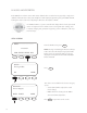
SETUP/FX/SEARCH------------search setup completed TOP SETUP MAIN Pressing TOP returns you to the SETUP/FX/ SEARCH screen. Pressing SETUP returns the user to the choose category screen. Pressing MAIN returns to the MAIN Menu. INPUT MENU The INPUT screens allow the user to choose either grid or generator AC input and the maximum amperage from either source that can pass through the FX before a warning occurs. MAIN-------------------------- From the MAIN screen, press SETUP .
SETUP/FX/INPUT----------P00 ac transfer Gen control DOWN GRID GEN PORT SETUP/FX/INPUT----------P00 ac1/grid 24.5 aac limit DOWN INC DEC PORT SETUP/FX/INPUT----------P00 ac2/gen 30.0 aac limit DOWN INC DEC PORT SETUP/FX/INPUT---------------input setup completed TOP To choose your AC input source in the ac transfer control screen, press GRID or GEN . Press DOWN to view the next screen.
ADVANCED SCREENS All the FX operation settings can be adjusted in the MATE’s ADVANCED screens, including some previously discussed in the INPUT and SETUP menus. Changing the settings under any menu will affect the values in all menus. The ADVANCED screens are accessed via the password 141.
INVERTER MENU The INVERTER screens allow adjusting the inverter’s operations to match the AC load and battery recharging requirements, including the search functions, low-battery cut-out, the FX’s output voltage, and resetting the FX to its factory default values. After entering the ADVANCED screens, press FX on the choose device screen.
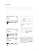
ADV/FX/INVERTER-------P00 search cycles pulse spacing DOWN INC 60 DEC PORT ADV/FX/INVERTER-------P00 low battery cut-out set point DOWN INC 10.5 vdc DEC PORT ADV/FX/INVERTER-------P00 low battery cut-in set point DOWN INC 12.5 vdc DEC PORT ADV/FX/INVERTER-------P00 adjust output voltage DOWN INC 11 230 vac DEC PORT The search pulse spacing screen adjusts the amount of time the FX waits before producing additional AC pulses to sense a load.
Use this screen to reset the FX to its factory default set points. This will cause all previous programming changes to be lost. Press MORE to choose the HUB port whose FX is to be reset and then press PORT or, if no HUB is in use, press NEXT . Press DOWN to skip resetting to factory defaults.
CHARGER MENU Each battery manufacturer has specific recharging directions and guidelines. OutBack’s default values work for many batteries, but might not be the ideal settings. The CHARGER Menu allows these settings to be adjusted. Please refer to your manufacturer’s recommendations. ADV From the ADVANCED menu, press FX . choose device: FX CC DC MATE ADV/FX/PAGE 1----------------- Press CHGR . choose category: ADV INV CHGR PG2 ADV/FX/CHARGER---------P00 charger limit DOWN INC 7.
ADV/FX/CHARGER---------P00 absorb time limit DOWN INC 01.0 hrs DEC PORT ADV/FX/CHARGER---------P00 float set point DOWN INC 13.6 vdc DEC PORT ADV/FX/CHARGER---------P00 float time period DOWN INC 01.0 hrs DEC PORT ADV/FX/CHARGER---------P00 refloat set point DOWN INC 12.2vdc DEC PORT The absorb time limit must be long enough for the batteries to regain 95-100% of their charge. This time limit can be set between 0 hours and 24 hours using INC and DEC .
ADV/FX/CHARGER---------P00 equalize set point 14.6 vdc DOWN INC DEC PORT ADV/FX/CHARGER---------P00 equalize time period DOWN INC 01.0 hrs DEC PORT ADV/FX/CHARGER-----------charger programming competed TOP 15 ADV MAIN An occasional equalize charge helps destratify the batteries for a longer working life. Pressing the AC IN hot key leads to screens that begin the equalize charge. The equalize set point determines the recharging voltage, which can range between 14.0VDC and 17.
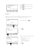
GENERATOR MENU OutBack FX and VFX Inverter/Chargers are programmed to use an AC generator as their default source of AC input. The CHARGER GEN screens allow a user to adjust the input voltage window and time delay of the AC input. ADV From the ADVANCED screen, press FX . choose device: FX CC DC MATE ADV/FX/PAGE 1----------------- Press PG2 .
ADV/FX/GEN---------------P00 ac2/gen lower limit DOWN INC 208 vac DEC PORT ADV/FX/GEN---------------P00 ac2/gen upper limit DOWN INC 270 vac DEC PORT ADV/FX/GEN---------------P00 ac2/gen input limit DOWN INC 7.0 aac DEC PORT ADV/FX/GEN---------------P00 ac2/gen transfer delay DOWN INC 17 60 cycles DEC PORT The ac/2 gen lower limit is the lowest allowable voltage for the FX to connect to the generator. If the voltage falls below this limit, the FX will disconnect from the generator.
ADV/FX/GEN---------------P00 ac2/gen support OFF DOWN OFF ON PORT ADV/FX/GEN-------------------GEN programming completed TOP ADV This feature is not operational at this time. Press DOWN to view the final GEN screen. MAIN Pressing TOP returns to the beginning of the ADV/FX/INVERTER menu. ADV returns to the ADVANCED screens and MAIN displays the MAIN screen.
FX SERIES INVERTER/CHARGER PROGRAMMING NOTE: Please see the International FX and VFX Series Inverter/Charger Installation Manual to install, wire, and connect each FX. This programming manual assumes all FXs have been installed and are ready to program according to the way they were wired. If a different programming is desired, the FXs might require a different wiring configuration (see sample wiring diagrams in the FX and VFX Series Inverter/ Charger Installation Manual).
COMPONENTS AND CONNECTIONS: 1. With all AC and DC breakers OFF, connect all FXs to the HUB with individual lengths of CAT5 cable.
2. With the FXs connected to the HUB, turn only the DC breakers ON and power up the components. All AC breakers should be OFF. NOTE: For 3-phase stacking, the jumper in the HUB must be set to the 3- ph position. See the HUB User Manual for further information.
3. After powering up the components, connect the MATE to the HUB. a) Plug the MATE into the 1st MATE Port on the HUB. b) The MATE will power up and should recognize any component connected to the HUB. c) The MATE can then program the FXs. d) The fifth MATE screen (Port Assignment) should display all the FXs and any OutBack Charge Controllers in the system. MATE Screens PATH G’day Mate (C) 2007 OutBack Version Searching Port Assignment Code a.
STACKING OPTIONS OutBack International Series FXs can be stacked in one of two configurations: 1. OutBack Parallel 2. 3-Phase NOTE: Although stacking 10 FXs is possible, OutBack’s AC hardware only accommodates configurations of two, four, or eight FXs. A system with eight FXs would require two AC Input/Output Bypass (IOB) Breaker Kits or installing an external manual bypass; ten FXs would require three IOB kits or an external manual bypass. 1.
2. 3-Phase • Three—and only three— FXs are connected, one to each of three 230 VAC output legs that produce 400 VAC between any two legs of the system. • The HUB requires a jumper between the two Slave FXs for this stacking to function (see HUB Communications Manager User’s Manual). • The AC input source (generator or grid) must be a 230VAC/400VAC 3-phase source.
2. Classic Slave • Classic Slave is the designation of the second FX in a two-inverter, split-phase system that produces 400VAC without using an FW-X240 Auto Transformer. • This FX is plugged into Port 02 of the HUB. This stacking option is not to be used in the International Series FX or VFX. OB Slave L1 and OB Slave L2 designations are used in OutBack Parallel Stacking or OutBack Series/ Parallel stacking 3.
PROGRAMMING THE FXS Once the MATE recognizes each FX (and OutBack Charge Controller), push and hold the first two soft keys simultaneously to return to the MAIN menu. To program the FXs, go to the ADV/FX/STACK menu on the MATE navigating with the following steps: MAIN-------------------------12:12:16A SUM STATUS SETUP ADV Press the soft key. NOTE: Pressing and holding the first two soft keys at the same time will always bring up the Main Menu screen.
ADV choose device: In the ADV menu, press the soft key. FX CC DC MATE ADV/FX/PAGE 1----------------choose category: ADV INV On the ADV/FX/PAGE 1 screen, press the soft key and go to the ADV/FX/PAGE2 screen. CHGR PG2 ADV/FX/PG2--------------------choose category: PG1 GRID Press the soft key which leads to the ADV/FX/PAGE3 screen. GEN PG3 ADV/FX/PAGE3-----------------choose category: PG2 27 AUX On the ADV/FX/PAGE3 screen, press the soft key.
ADV/FX/STACK--------P01 stack phase 1-2ph DOWN INC Master DEC PORT ADV/FX/STACK------------P01 stack phase 1-2ph DOWN INC Stacking the FX Series Inverter/Chargers begins on this screen. See specific stacking procedures in the next section. Master DEC PORT Port 01 always takes the Master FX. Pressing the soft key changes the HUB Port whose value you wish to adjust. Pressing the or soft keys changes the stacking phase.
1-2PH MASTER With the Port 01 FX as the Master, press the soft key to change the remaining Ports and designate the remaining FXs as Slaves. The MATE screen for Port 02 will look like this: ADV/FX/STACK---------P02 stack phase 1-2ph DOWN INC Master DEC PORT ADV/FX/STACK----------P02 stack phase Classic DOWN INC Slave DEC PORT • The MATE is now ready to program the FX plugged into Port 2 of the HUB. • 1-2ph Master is the factory default value for each FX.
ADV/FX/STACK----------P02 stack phase OB Slave L1 OB Slave 1 stacking phase DOWN INC DEC PORT OUTBACK (OB) SLAVE L2 • Set the FXs you want as series slaves (Leg 2) to OB Slave L2. • This FX is considered the L2 phase. ADV/FX/STACK----------P02 stack phase OB DOWN INC Slave DEC L1 PORT To use OutBack Slave L2 Stacking, press the soft key in the ADV/FX/STACK OB screen to change the stack phase from OB Slave L1 to OB Slave L2.
ADV/FX/STACK----------P01 stack phase DOWN INC 3ph Master The FX has now been set to 3ph Master status. DEC PORT 3-PHASE (3-PH) SLAVE • Set the two Slave FXs to 3ph Slave and make sure they are in Ports 02 and 03 of the HUB. • There are no selections to differentiate between phases B and C. • When you set the jumper in the HUB for 3-phase, the HUB assigns each Slave to its phase. 3ph Slave on HUB Port 2 is considered phase B. • 3ph Slave on HUB Port 3 is considered phase C.
INTRODUCTION TO POWER SAVE LEVELS Depending on the model, each FX consumes 20-25 watts of power when it remains on, even if it isn’t actively inverting or charging. OutBack Power Systems offers the option to shut down (put into Silent mode) some or all of the Slave FXs until the loads require them to come on again. • When a load exceeds six amps AC, the Master FX shares the load with one or more Slave FXs.
ADV/FX/STACK------------P02 power save level slave adjust only 1 DOWN INC DEC PORT ADV/FX/STACK----------------stacking setup completed TOP 33 ADV MAIN The default value for the power save level slave adjust only screen is 1. Press the or soft keys to adjust this value. Press the soft key to change the value of each Slave FX. • The Slave(s) must be connected to Port 2 or higher on the HUB.
POWERING UP With the programming completed, turn the AC output breakers ON with the AC BYPASS on the AC breaker panel switched to NORMAL. BYPASS OUTPUT INPUT Verify the AC voltage output through the MATE following path: PATH MAIN--------------------12.15:30p SETUP-----------choose device: SUM STATUS SETUP ADV FX CC DC MAIN STATUS/FX/PAGE1---------choose category: Float P00 inv 0.0Kw zer 0.0kw chg 0.0kw buy 0.
Turn the AC input breakers ON. BYPASS OUTPUT INTPUT If the FX’s AC source is available, the yellow AC IN STATUS light will blink. The FX will connect to the utility grid when the voltage is within 200-260 VAC and the frequency between 45-55 Hz. After about 30 seconds, the AC IN light should stop blinking and stay lit. The FX will now perform a battery charge using the available AC.
STACKING SYSTEM EXAMPLES OutBack Parallel Stacking • Four FXs in a single system are referred to as a Quad Stack. • The FX installed at the bottom of the stack is plugged into Port 1 of the HUB. • The second, third, and fourth FXs are plugged into Ports 2, 3, and 4 respectively. PRESS UNTIL 141, THEN PRESS ENTER.
RANKING THE SLAVES Start from the last ADV/FX/STACK screen. ADV/FX/STACK----------P04 ADV/FX/STACK----------P04 ADV/FX/STACK---------P02 stack OB Slave phase power save level slave adjust only power save level slave adjust only DOWN INC L1 DEC PORT Press the soft key 2 times to the power save level slave adjust only menu. DEC PORT Press the soft key until P02 is displayed. This menu pertains to the Slaves only. The default setting should be 1 which is the 1st rank Slave.
After setting up your OutBack Parallel Stacking and establishing the Master and Slave order, shut off all the AC input and output breakers and check your system via the following MATE screens: ADV/FX/STACK---------P04 ADV/FX/STACK--------------- ADV/FX/STACK---------P04 power save level slave adjust only stacking setup completed stack OB Slave phase TOP ADV MAIN DOWN INC DOWN INC 3 DEC PORT L1 DEC PORT From the ADV/FX/STACK power save level slave adjust only screen, press the soft key,
3-Phase Stacking (Three FX Series Inverter/Chargers Only) A 3-phase stacked system with only three FXs must be set up as described here: • Turn off all AC output and AC input breakers before powering up FXs. • Plug the top FX into Port 01 of the HUB, the 2nd FX into Port 02, and the 3rd FX into Port 03. • Change the HUB jumper for 3-phase stacking (refer to the HUB manual). • Go to the first MATE stacking menu (Stack Phase) press the soft key until Port 01 appears.
ADV/FX/STACK--------P02 ADV/FX/STACK--------P02 ADV/FX/STACK--------P03 stack 1-2ph phase 3ph Slave stack phase DOWN INC DEC PORT DOWN INC DEC PORT Master DOWN INC DEC PORT PRESS INC FIVE TIMES 1-2ph Master PRESS INC FIVE TIMES ADV/FX/STACK---------P03 stack phase 3ph Slave DOWN INC DEC PORT PRESS DOWN THREE TIMES AUXILIARY (AUX) FUNCTIONS The AUX output provides a 12VDC, 0.7ADC max output at the AUX terminals to control DC or AC external loads.
ADV/PASSWORD enter the password 132 ENTER INC The screen displays <132>. Press the soft key until it scrolls to the password 141. DEC EXIT ADV/PASSWORD enter the password Push the soft key. 141 ENTER INC DEC EXIT ADV choose device: FX CC In the ADV menu, press the soft key. DC MATE ADV/FX/PAGE 1 ---------------choose category: On the ADV/FX/PAGE 1 screen, press the soft key and go to the ADV/FX/PAGE2 screen.
ADV/FX/PG2--------------------choose category: PG1 GRID Press the soft key which leads to the ADV/FX/PAGE3 screen. GEN PG3 ADV/FX/PAGE3----------------choose category: PG2 AUX STACK PG4 ADV/FX/AUX--------------P00 aux output control DOWN INC AUTO DEC PORT On the ADV/FX/PAGE3 screen, press the soft key to adjust the AUX output set points and operation. Selecting the or soft keys changes the mode of the AUX.
LIST OF AUX FUNCTIONS • Cool Fan activates the standard TurboFan which cools the FX during an over temperature condition. • Divert DC and Divert AC allows the AUX to divert excess renewable energy to a DC or AC load, respectively. This allows control of energy sources such as wind turbines or hydro-generators. When using Divert AC, the AUX output will shut off if the inverter is overloaded. • AC Drop is activated when an AC power source disconnects from an FX.
ADV/FX/AUX-------------P00 aux output function DOWN INC Remote DEC PORT ADV/FX/AUX---------------P00 genalert on set point DOWN INC 11.5vdc DEC PORT ADV/FX/AUX---------------P00 genalert on delay DOWN INC 4 minutes DEC PORT ADV/FX/AUX---------------P00 genalert off set point DOWN INC 14.0 vdc DEC PORT From the Remote aux output function screen, press the soft key. This will bring up the first of several screen used to adjust which ever mode you have chosen for the AUX function.
After a battery has recharged or returned to ADV/FX/AUX--------------P00 the genalert off set point, genalert off delay genalert off delay determines the amount of time the generator DOWN INC 9 min remains on to assure the battery has been more DEC PORT fully recharged. The user can adjust this time from 0-240 minutes in using the and soft keys. Press the soft key to view the loadshed off set point screen.
ADV/FX/AUX---------------P00 diversion on set point DOWN INC 14.6 vdc DEC PORT ADV/FX/AUX--------------P00 diversion off delay 30 sec DOWN INC DEC PORT After deciding on Divert DC or Divert AC in the AUX output function screen, use the diversion on set point screen to choose the voltage which will activate this function. This value can range from 12.0VDC-16.0VDC and can be adjusted in 0.1 VDC increments using the and soft keys.
BATTERY CHARGING INSTRUCTIONS Battery Charging Set Points Recharging set points are programmed using the OutBack MATE in the ADV/FX/CHARGER screens. The MATE comes set with default charging values found in the CHARGER menu (see page 13). These values might not be the best for your specific batteries and can result in uneven recharging.
Battery Charging Sequence 1. BULK • FX uses as much AC current as possible to raise the battery voltage to ABSORB (time period for BULK charging varies) voltage level. 2. ABSORB • FX uses as much AC as necessary to maintain the ABSORB voltage for the ABSORB TIME (default is one hour), decreasing the AC current as the ABSORB charge continues. 3. SILENT • The first SILENT mode follows ABSORB. During this time, the FX charging operation stops, but continues monitoring the battery voltage.
• • • • 49 External DUMP LOAD is Limiting Battery Voltage: Wind turbines and micro-hydro systems can produce very high voltages depending on wind and water velocity. These voltages can damage batteries. Battery-determined DUMP LOADS bleed off this excess voltage. The DUMP voltage can be below the target voltage (ABSORB, FLOAT, or EQUALIZE) the FX is trying to reach, preventing the FX from reaching these voltage set points. The FX will continue to charge while the DUMP load continues to absorb voltage.
FX Default Values (subject to change with FX upgrades) Correction Factor • 24VDC: Multiply 12VDC values by 2 • 32VDC: Multiply 12VDC values by 2.64 • 48VDC: Multiply 12VDC values by 4 12 VDC System DEFAULT MINIMUM MAXIMUM Float Voltage 13.6V 12V 15V Absorb Voltage 14.4V 13V 16V EQ Voltage 14.4V 14V 17V ReFloat 12.5V 11V 13V LBCO 10.5V 9V 12V LBCI 12.
TWO YEAR LIMITED WARRANTY INFORMATION FX Series Inverter/Charger Products OutBack Power Systems, Inc. (“OutBack”) provides a two year (2) limited warranty (“Warranty”) against defects in materials and workmanship for its FX/VFX Series Inverter/Charger products (“Product(s)”) if installed in fixed location applications. The term of this Warranty begins on the Product(s) date of manufacture or the initial purchase date as indicated on the warranty registration card submitted to OutBack, whichever is greater.
To request warranty service, you must contact OutBack Technical Services at 360.435.6030 (North America), +34.93.654.9568 (Europe), or support@outbackpower.com within the effective warranty period. OutBack Technical Support will attempt to troubleshoot the product and validate that the failure is product related. If warranty service is required, OutBack will issue a Return Material Authorization (RMA) number. A request for an RMA number requires all of the following information: 1.
LIMITED WARRANTY REGISTRATION Complete this form to request a Limited Warranty, and return it to: Outback Power Systems Inc. 19009 62nd Ave. NE Arlington, WA 98223 NOTE: Please submit a copy (not the original) of the Product purchase invoice, which confirms the date and location of purchase, the price paid, and the Product Model and Serial Number.
54
Corporate Headquarters 19009 62nd Avenue NE Arlington, WA 98223 USA Phone: (+1) 360.435.6030 www.outbackpower.com 55 European Sales Office C/ Castelló, 17 08830 - Sant Boi de Llobregat BARCELONA, España Phone: +34.93.654.