
1100RE 24 VDC 960 Ah Battery Bank Installation


Page 12 Publication No. US-DDm-IM-003
www.enersysinc.com November 2003
4. Slide the module back into a safe position.
Remove the shipping retainer.
5. Slide module completely into position so the
lip of the module touches the front of the
shelf.
6. Place another cell onto the shelf next to the
previously placed battery sleeve. Refer to
the Assembly Drawing for the cell polarity
configuration. See Figure 19.
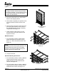
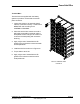
7. Install remaining cells working from the
lower shelves to the higher shelves. See
Figures 20 and 21.
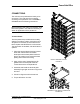
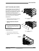
Module Retainers
1. For each battery module, install retainer
plates and spacers as required, using a
M10x1.5 – 25mm Serrated Hex Bolt. See
Figure 22.
2. Torque to 20 ft-lbs.
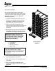
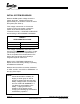
Electrical Bonding Instructions
1. For each battery module, install (1) M6 Self-
Tapping Screw through front lip of the
battery module into the shelf/horizontal
channel. See Figure 23.
2. For each retainer spacer, install (1) M6 Self-
Tapping Screw through the spacer into the
shelf/horizontal channel. See Figure 23.
INSTALL BONDING SCREWS
FIGURE 23
NOTE:
The top row of the rack requires spacers to be
installed behind the upper lip of the battery
modules. This spacer is fastened into place
with the retainer and retainer bolt.
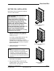
NOTE:
The larger modules are too heavy to lift onto
the shelves manually. To avoid personal injury
use appropriate lifting devices when lifting
modules onto the shelves.
INSTALL MODULES
FIGURE 21
INSTALL RETAINERS
FIGURE 22