EnergyCell Battery Owner’s Manual
About OutBack Power Technologies OutBack Power Technologies is a leader in advanced energy conversion technology. OutBack products include true sine wave inverter/chargers, maximum power point tracking charge controllers, and system communication components, as well as circuit breakers, batteries, accessories, and assembled systems. Audience This manual is intended for use by anyone required to install and operate this battery.
Table of Contents Important Safety Instructions ........................................................................ 4 Additional Resources .......................................................................................................................................................... 4 EnergyCell Batteries ...................................................................................... 5 Welcome to OutBack Power Systems ...................................................................
Safety Instructions Important Safety Instructions READ AND SAVE THESE INSTRUCTIONS! This manual contains important safety instructions for the EnergyCell battery. These instructions are in addition to the safety instructions published for use with all OutBack products. Read all instructions and cautionary markings on the EnergyCell battery and on any accessories or additional equipment included in the installation. Failure to follow these instructions could result in severe shock or possible electrocution.
EnergyCell Batteries Welcome to OutBack Power Systems Thank you for purchasing the OutBack EnergyCell battery. EnergyCell is a series of absorbed glass-mat (AGM) batteries with a valve-regulated lead-acid (VRLA) design. They are designed to provide long, reliable service with minimal maintenance. Several versions are available, including front-terminal and top-terminal designs. All have high recharge efficiency and a compact footprint for higher energy density.
Installation and Operation EnergyCell RE The EnergyCell RE (Renewable Energy) Series uses pasted lead-calcium-tin plates. It is designed for regular discharge/charge cycles. The EnergyCell RE is available in both top-terminal and front-terminal designs.
EnergyCell Batteries EnergyCell GH Front Terminal The EnergyCell GH (Grid/Hybrid) Series uses a unique lead plate technology called thin-plate pure lead (TPPL). It is intended to receive continuous float charging under normal conditions when utility power is present.
Installation and Operation Accessories Interconnect bar (provided with front terminal batteries only) Terminal cover (provided with front terminal batteries only) Hardware kit Interconnect cables as needed CAUTION: Fire Hazard Install properly sized battery cabling and interconnect cables. The cable ampacity must meet the needs of the system, including temperature, deratings, and any other code concerns.
EnergyCell Batteries Stored batteries should be checked for open-circuit voltage at intervals. Any time the battery voltage is less than 2.10 Vpc (volts per cell; this equates to 12.6 volts per battery), it should be given a freshening charge regardless of the storage time. At 104°F (40°C), the EnergyCell GH voltage should be checked every 2 months. At 86°F (30°C), the interval is 3 months. At 77° to 68°F (25° to 20°C) the interval is 4 months.
Installation and Operation System Layout CAUTION: Fire Hazard Failure to ventilate the battery compartment can result in the buildup of hydrogen gas, which is explosive. The battery enclosure or room must be well-ventilated. This ventilation protects against accidental gas buildup. All EnergyCell batteries are valve-regulated and do not normally emit noticeable amounts of gas. However, in the event of accidental leakage, the enclosure must not allow the leaked gas to become concentrated.
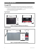
EnergyCell Batteries Batteries are placed in parallel (positive to positive, negative to negative) for additive amp-hour capacity. Three batteries in parallel have three times the amp-hours of a single battery. However, batteries in parallel do not have additive voltages. A single set of batteries in parallel (as shown in this figure) have the same voltage as a single battery.
Installation and Operation DC Wiring CAUTION: Equipment Damage Never reverse the polarity of the battery cables. Always ensure correct polarity. CAUTION: Fire Hazard Always install a circuit breaker or overcurrent device on the DC positive conductor for each device connected to the batteries. CAUTION: Fire Hazard Never install extra washers or hardware between the mounting surface and the battery cable lug or interconnect. The decreased surface area can build up heat.
EnergyCell Batteries To make the DC connections: Make certain to clean all terminals and contact surfaces according to the steps on page 12. 1. 3. If installing batteries in a rack or cabinet, always begin with the lowest shelf for stability. Place all batteries with terminals facing to the most accessible side of the rack. If terminal protectors are present, remove and save them. In common configurations, the battery on one end will be the positive (+) output for that string.
Installation and Operation Commissioning EnergyCell RE or EnergyCell NC The commissioning charge applies when the batteries have been in storage or transit for an extended period. It also applies when the battery system is intended for use at the minimum float charging voltage or when the number of cells in series is greater than 24. Under any of these conditions, it is recommended the battery system be given a freshening charge at 2.4 volts average per cell for 24 hours.
EnergyCell Batteries Charging (EnergyCell RE & NC) EnergyCell RE batteries are usually charged using a “three-stage” charging cycle: bulk stage, absorption stage, and float stage. Most OutBack chargers follow this algorithm. However, not all chargers are designed or programmed the same way. The settings should be checked and changed to match the recommendations below if necessary. Contact OutBack Technical Support before using other charger types. Bulk Stage The bulk stage is a constant-current stage.
Installation and Operation The voltage requirements for float stage are much lower than for bulk and absorption. The voltages per model of EnergyCell RE or EnergyCell NC are listed in Table 5 on page 21. The float stage should provide enough current to maintain the appropriate voltage. If batteries are in series, this number should be multiplied by the number of batteries in the string. Freshening Charge A maintenance or “freshening” charge is given to batteries that have been in storage.
EnergyCell Batteries Charging (EnergyCell GH) EnergyCell GH batteries are usually charged using a constant-voltage or float charger. OutBack inverter/chargers and charge controllers do not have this function as their default setting. They can be made to perform a constant float charge by skipping the absorption stage or setting the absorption voltage equal to the float voltage. Other adjustments may be necessary.
Installation and Operation Remote Temperature Sensor OutBack inverter/chargers and charge controllers are equipped with the Remote Temperature Sensor (RTS) which attaches to the battery and automatically adjusts the charger settings. When the RTS is used, it should be placed on the battery sidewall, as close to the center of the battery (or to the center of the bank) as possible. The charger determines the RTS compensation factor. Most OutBack chargers are preset to a compensation of 5 mV per cell.
Troubleshooting and Maintenance Table 1 Category Symptom Troubleshooting Possible Cause Remedy Normal life cycle Replace battery bank when (or before) capacity drops to unacceptable levels. Defective cells Test and replace battery as necessary. Excessively cold battery Carefully warm up the battery. Undersized cabling Increase cable ampacity to match loads. Loose or dirty cable connections Check and clean all connections. Physical damage on terminals may require the battery to be replaced.
Maintenance Periodic Evaluation Upon replacement of a battery (or string), all interconnect hardware should be replaced at the same time. To keep track of performance and identify batteries that may be approaching the end of their life, perform the following tests during on a quarterly basis following commissioning (see page 14). Tests must be made with a high-quality digital meter. Voltages must be measured directly on battery terminals, not on other conductors.
Specifications Table 2 EnergyCell Battery Electrical Specifications EnergyCell RE and EnergyCell NC (all models) EnergyCell GH (all models) Valve-regulated, lead-acid (VRLA) Valve-regulated, lead-acid (VRLA) Absorbed glass-mat (AGM) Absorbed glass-mat (AGM) 6 6 Battery Category Battery Technology Cells Per Unit Voltage Per Unit (nominal) Operating Temperature Range (with temperature compensation) 12 Vdc 12 Vdc Discharge: -40°F (-40°C) to 160°F (71°C) Charge: -10°F (-23°C) to 140°F (60°C) -40°F
Specifications Ampere-Hour Capacity Based On Discharge Rate The EnergyCell battery capacity is measured in amp-hours. The battery capacity is not a fixed number, but will vary with conditions. (See page 9.) The figures in the tables below are used to measure the capacity of the EnergyCell battery based on load size. Battery capacity is judged by the number of amp-hours measured when a battery is discharged to a standard voltage under load. This is known in the industry as “terminal voltage”.
Specifications This page intentionally left blank.
Masters of the Off-Grid.™ First Choice for the New Grid. Corporate Headquarters 17825 – 59th Avenue N.E. Suite B Arlington, WA 98223 USA +1.360.435.6030 900-0127-01-00 Rev E European Office Hansastrasse 8 D-91126 Schwabach, Germany +49.9122.79889.