
Manual


Installation
12
900-0253-01-00 Rev A
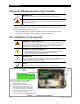
Wiring
This section provides instructions on installing PV array wiring into the charge controller. See page 67 for
more notes on PV array sizing. All wiring must comply with local and national codes.
Grounding
This product is intended to be installed as part of a permanently grounded electrical system. This
grounding is shown in the wiring diagrams in this book. Grounding methods must comply with local and
national codes.
The FLEXmax 100 equipment ground is marked with this symbol:
IMPORTANT:
The FLEXmax 100 includes internal ground-fault protection and meets the requirements of
the 2017 National Electric Code, Article 690.41(A)(1) for two-wire PV arrays with one
functional grounded conductor.
Bonding one of the battery conductors to ground is required for NEC compliance and is
strongly recommended in any case. The product comes with a functional bond
established from negative to ground. For positive-ground installation, see page 13.
The battery conductor (positive or negative) must be bonded to the grounding system at
only one point. An external bond should not be present elsewhere in the system unless
the bond in the FLEXmax 100 is intentionally removed. If present, another bond will
defeat the GFDI protection. See page 14.
If required, external ground-fault protection can be used with this product, such as the
OutBack GFDI or PV system grounding in compliance with NEC 690A)(5). See page 14.
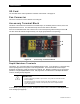
Make certain to connect the FLEXmax grounding terminal bus bar to earth ground. See
Figure 7 on page 16 for the location. Failure to do so may cause a ground fault error.
CAUTION: Equipment Damage
See page 13 for instructions when installing the FLEXmax 100 in a positive-ground
system. These include, but are not limited to:
~
Any GFDI protection must be external. The FLEXmax 100 internal GFDI must be
disabled prior to use in a positive-ground system.
~
The FLEXmax 100 cannot be networked in a positive-ground system with multiple
inverters. In a positive-ground system, it can only be used with one OutBack inverter
and one HUB communications manager.
~ For use of the FLEXnet DC Battery Monitor or other devices in these applications,
see page 72.
Failure to follow these instructions can damage the controller and other devices.
This damage is not covered under warranty.
Negative-Ground Systems
WARNING: Shock Hazard
Failure to bond one battery conductor to the grounding system can present a risk of
electric shock.
CAUTION: Equipment Damage
Failure to follow ground bonding instructions can damage the FLEXmax 100 and other
devices. This damage is not covered under warranty. Failure to follow these instructions may
also result in noncompliance with NEC or other codes.
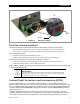
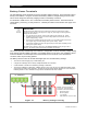
The FLEXmax 100 uses a jumper wire to create a functional ground for one conductor. Connecting this
wire completes a mechanical connection (bond) between one battery conductor and the ground. The
default position creates a negative-to-ground bond, the most common configuration (item A in Figure 5).
The negative jumper position also completes a connection to the internal ground fault detection and
interruption (GFDI) circuit through the GFDI fuse. The jumper is removed if an external GFDI device is
used. See the GFDI section on page 13.