
Manual

Status and Information
900-0253-01-00 Rev A
31
Modes of Operation
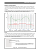
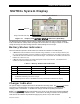
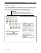
The FLEXmax 100 goes through many states during its operation. Figure 21 shows an example of the
various stages of battery charging and several states when the controller is not charging. The graph in
Figure 21 shows a typical day of charging with a nominal 48-volt system. Charging is described in detail
on page 69.
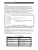
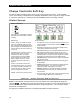
A MATE3s system display has five “mode” messages which represent all controller states of operation.
The following sections use the names displayed by the system display (see page 36). These sections
describe the controller operation and show the LED indicators illuminated in each mode.
Figure 21 FLEXmax 100 Battery Charging and Modes
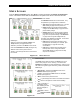
Bulk
This is a Maximum Power Point Tracking mode which harvests the maximum wattage available from the
PV array. The controller will drive the battery voltage towards the Absorb Voltage set point. Normally
the charge controller enters this mode at the beginning of the day or when a new charge cycle begins.
The controller may also enter this stage if there is not enough PV energy to maintain a different stage
such as Absorption. See page 32 for more information.
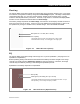
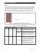
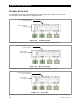
Figure 22 LED Indicators (Bulk)
Blue (solid)
Amber (solid)
The S
TATUS indicator will remain amber as long as the battery voltage remains
above 1.91 Vpc, even if no charging is occurring. The C
HARGING indicator,
however, will not illuminate if less than 10 watts is used by the PV. This may
occur if charging is performed by another source.