
Flexnet User Manual

Page 2 Page 3
900-0093-12-00 Rev C
©2020 OutBack Power. All Rights Reserved.
Specifi cations Installation
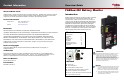
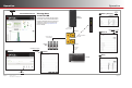
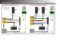
Installing the FLEXnet DC
The FLEXnet DC mounts in a ¾" DC circuit breaker slot installed inside an OutBack Power load center.
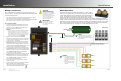
To mount the FLEXnet DC inside an OutBack Power enclosure:
1. Put the system into bypass mode.
2. Shut off all AC input to inverters.
3. Shut off all PV and DC breakers.
4. Disconnect the battery cables at the battery.
5. Remove the breaker bracket from its enclosure by removing the four corner screws.
6. Remove one of the DC breaker knockouts.
7. Insert the FN-DC unit into the rear of the breaker bracket so that the indicator lights fi t in the breaker opening.
8. Mount the FN-DC securely using the two #6-32 screws provided.
Remove breaker knockout and install FN-DC
using 2 #6-32 × ⅜" pan-head machine screws
provided (torque to 5 to 8 inch-pounds).
The FN-DC mounting location will vary depending on
the system. Here, for example, in the GSLC, the
FN-DC is mounted adjacent to the main DC breakers
for the battery bank.
0.7" (1.9 cm)
3.7" (9.4 cm)
6.6"
(16.8 cm)
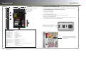
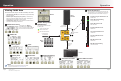
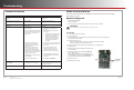
Features
A: State of Charge Indicator Lights
B: Mounting Screws
C: Hub Cable Port
D: Wiring Block
Specifications
Battery Voltage Input Range................. 8 to 80 Vdc
Battery Voltage Resolution ................... 0.1 Vdc
Number of Current Channels................ 1 to 3 (source or load)
Current Range (Each Channel) ............ +/- 1000.0 amps DC
Current Resolution................................ 0.1 amps DC
State of Charge Display........................ 0 to 100% (1% increments)
Aux Relay Confi guration ....................... SPST magnetic latching relay
Aux Relay Max Rating .......................... 5 amps @ 30 Vdc
Current Shunt Type (not incl.) ............... 500A / 50 mV
Display .................................................. MATE3s (not included) / LED indicators on unit
Battery Amp Hour Capacity Range ...... 100 to 10,000 AH
Data Logging Memory .......................... Most recent 128 days
Programmable Aඝච Relay Settings ...... 8 to 80VDC / 0 to 100% SOC / 0 to 240 minutes
Accuracy ............................................... 0.5% of reading
Operating Temperature Range ............. 0 to 50°C / 32 to 122°F
Mounting ............................................... ¾" panel mount breaker slot or surface mount using built-in mounting bars
Warranty ............................................... Standard 5 year
Weight .................................................. 5 oz (0.14 kg)
Dimensions ........................................... 0.7 × 3.7 × 6.6ʺ (1.9 × 9.4 × 6.8 cm)
C
D
B
A
B