
Installation Guide

Installation
18
900-0168-01-00 Rev C
Wiring
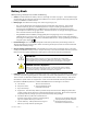
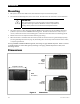
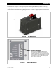
It will be necessary to remove knockouts from the AC Plate to run wires. The AC Plate has one
knockout of ½” size and two knockouts of ¾” size. Install appropriate bushings to protect the wires.
Use copper wire only. Wire must be rated at 75°C or higher.
Grounding
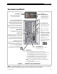
WARNING: Shock Hazard
This unit meets the IEC requirements of Protection Class I.
The unit must be connected to a permanent wiring system that is grounded
according to the IEC 60364 TN standard.
The input and output circuits are isolated from ground. The installer is responsible for
system grounding according to all applicable codes.
For safety, the neutral and ground conductors should be mechanically bonded.
OutBack does not bond these conductors within the inverter. Some codes require
the bond to be made at the main panel only. Make sure that no more than one bond
is present in the AC system at any time.
WARNING: Shock Hazard
For all installations, the negative battery conductor should be bonded to the grounding
system at only one point. If the OutBack GFDI is present, it can provide the bond.
IMPORTANT:
Not all OutBack products can be used in a positive-ground system. If it is necessary to
build a positive-ground system with OutBack products, contact OutBack Technical
Support at +1.360.618.4363 before proceeding. Additionally, consult the online forum
at www.outbackpower.com/forum/, where this subject has been discussed extensively.
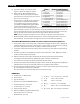
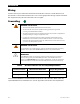
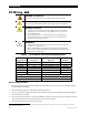
Table 4 Ground Conductor Size and Torque Requirements
Terminal Location Minimum Conductor Size Torque Requirements
Central AC Terminals
6 mm or #10 AWG (0.009 in) 2.8 Nm (25 in-lb)
DC Box Lug
16 mm or #6 AWG (0.025 in) 5.1 Nm (45 in-lb)
Table 4 contains OutBack’s recommendations for minimum safe cable sizes. Other codes may
supersede OutBack’s recommendations. Consult applicable codes for final size requirements.