
Installation Guide


Installation
20
900-0160-01-01 Rev B
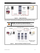
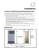
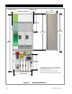
Figure 9 Mounting the Inverter
Radian
Mountin
g
x x
3. Align the left edge of the inverter with the left edge of
the mounting plate. This will expose the right edge of
the plate, allowing easy installation of another Radian
inverter/charger in the future. All additional inverters
are mounted to the right of the existing unit.
The unit shown to the right is not aligned with the
mounting plate, as the plate is still visible. In this
example, it should slide to the left so that the plate is
entirely covered.
NOTE: If the GS Load Center is used with
the Radian inverter, the following step should
be omitted.
4. Once aligned, secure the Radian inverter
to the stud using a lag screw (provided) in the left
corner of the inverter’s bottom flange.
Securing the inverter this way will prevent it from
dislodging from the mounting plate in the event of an
earthquake or similar event.
NOTE: The left corner is used for securing the
inverter to a stud. If the Radian inverter is mounted
on plywood or a similar wide-area mounting surface
as shown, any of the slots in the mounting flange
may be used.
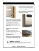
2. Place the Radian inverter against the wall and slide
it directly over the upper lip of the mounting plate.
The inverter’s mounting flange should come to rest
within the lip so that it hangs securely.
To assist in alignment, dimples have been placed
on the side of the unit to mark the lower edge of the
flange. In the picture to the left, the two x symbols
show the location of the dimples.
WARNING: Shock Hazard
When the inverter is used with other metal chassis, make sure that all chassis are grounded
appropriately. (See the grounding instructions on page 24.) Grounding other chassis may
involve metal-to-metal contact or separate ground wires.
…continued from the previous page…