
Installation Guide


Installation
900-0160-01-01 Rev B
21
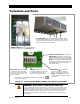
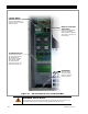
Component Mounting
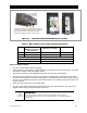
Figure 10 Mounting for System Components
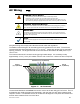
For the FLEXmax charge controller:
To fit on the inverter’s right side, FLEXmax
charge controllers require the FW-CCB or
FW-CCB2 mounting brackets. To assist
many possible mounting requirements, four
sets of mounting holes have been provided
for the brackets.
For the MATE3s:
To fit on the Radian
inverter’s left side, the
MATE3s requires the
FW-MB3 mounting bracket.
Holes are provided on the
upper and lower left side
to attach the FW-MB3.
For more information,
see the FW-MB3
instruction sheet.
For the HUB:
To fit on the Radian inverter’s left
side, the HUB uses two mounting
holes and three knockouts.
NOTE
: The OutBack FLEXmax 100 should be installed on the wall to either side of
the GSLC for direct wirin
g
access and does not re
q
uire additional brackets.
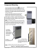
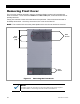
The top of the GS Load Center (GSLC) connects to the
bottom of the Radian inverter using four keyhole slots. The
keyhole slots fit over four screws on the bottom of the inverter
that secure the GSLC to the inverter when tightened. (The long
screwdriver recommended on page 19 may be needed to reach
these screws.) The GSLC should be secured to the wall using
screws or wall anchors.
The GSLC also makes a mechanical connection to the
Radian using bus bars that bolt to the inverter’s DC
terminals. Other connections are wired as necessary.
Several system components can mount directly onto the
Radian inverter or the GSLC. A MATE3-class system display
and the HUB Communications Manager can easily be mounted
on the left side of the system. FLEXmax charge controllers
can be mounted on its right side.
NOTE
: The FLEXmax controller requires mounting brackets
(see below). The conduit provided with these brackets is long
enough to wire the FLEXmax directly to the GSLC. Additional
conduit may be necessary when mounting on the inverter.
The image on the right shows GSLC mounting. See Figure 2
on page 7 for other configurations.