
Installation Guide


Installation
900-0160-01-01 Rev B
25
Wiring
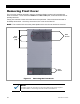
It will be necessary to remove knockouts from the chassis to run wires. Bushings are included with
the hardware kit to protect the wires. Make sure to install these bushings in the holes.
Use copper wire only. Wire must be rated at 75°C or higher.
Grounding
WARNING: Shock Hazard
This unit meets the IEC requirements of Protection Class I.
The unit must be connected to a permanent wiring system that is grounded according to
the IEC 60364 TN standard.
The input and output circuits are isolated from ground. The installer is responsible for
system grounding according to all applicable codes.
For safety, the neutral and ground conductors should be mechanically bonded. OutBack
does not bond these conductors within the inverter. Make sure that no more than one
bond is present in the AC system at any time. Some codes require the bond to be made
at the main panel only.
The GS Load Center (GSLC) is equipped with a neutral-ground bond. If bonding is
required to be in another location, the bond in the GSLC may need to be removed.
WARNING: Shock Hazard
For all installations, the negative battery conductor should be bonded to the grounding system
at only one point. If the OutBack GFDI is present, it provides the bond. (The GSLC is also
equipped with its own bond, which may need to be removed.)
IMPORTANT:
Most OutBack products are not designed for use in a positive-grounded system. If it is
necessary to build a positive-grounded system with OutBack products, see the
Positive
Grounding
applications note at
www.outbackpower.com
.
Table 3 Ground Conductor Size and Torque Requirements
Terminal Location Minimum Conductor Size Torque Requirements
Ground TBB #8 AWG (0.013 in²) or 10 mm² 25 in-lb (2.8 Nm)
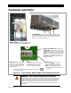
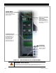
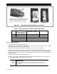
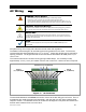
Figure 14 Chassis Ground TBB
The inverter’s ground terminal bus bar (TBB)
may be used for making all ground
connections to other parts of the system.
Examples include inverter equipment
grounding, generator grounding, load panel
grounding, and main earth ground wire. When
the GSLC is used, make a connection from the
inverter to the ground TBB in the GSLC.
This TBB accepts up to #4 AWG (0.033 in²) or
25 mm² wire.