
Installation Guide


Installation
26
900-0160-01-01 Rev B
DC Wiring
WARNING: Shock Hazard
Use caution when working in the vicinity of the inverter’s battery terminals.
CAUTION: Equipment Damage
Never reverse the polarity of the battery cables. Always ensure correct polarity.
CAUTION: Fire Hazard
The installer is responsible for providing overcurrent protection. Install a
circuit breaker or overcurrent device on each DC positive (+) conductor to protect
the DC system.
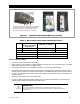
Never install extra washers or hardware between the mounting surface
and the battery cable lug. The decreased surface area can build up heat.
See the hardware diagrams on page 28.
IMPORTANT:
The DC terminals must be encased in an enclosure to meet NEC requirements.
The GS Load Center (GSLC) meets this requirement.
Table 4 contains OutBack’s recommendations for minimum cable sizes. Other codes
may supersede OutBack’s requirements. Consult local codes for final size
requirements.
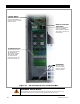
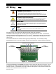
The following notes are depicted in Figure 15 on the next page.
IMPORTANT:
The Radian GS8048A contains two internal power modules, each with its own set
of DC terminals. Both sets of terminals
must
be connected to battery power for the
inverter to work correctly.
The Radian GS4048A contains a single power module which occupies the space
on the left. Although it has two pairs of terminals, only the pair on the left is
functional. The battery cables must be connected to these terminals. The
terminals on the right
must not
be connected to battery power.