
Installation Guide


Installation
900-0160-01-01 Rev B
27
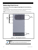
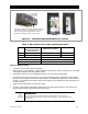
Figure 15 GS8048A and GS4048A Battery Terminals
Table 4 DC Conductor Size and Torque Requirements
Inverter Nominal DC Amps
(Minimum, per breaker)
(Derated 125%)
Conductor Size
(Minimum, per breaker)
Breaker Size
GS8048A 104 2/0 AWG (0.109 in²) or 70 mm² 175 Adc/AIC 10kA
GS4048A 104 2/0 AWG (0.109 in²) or 70 mm² 175 Adc/AIC 10kA
Terminal Location Torque Requirements
Inverter DC Terminals 60 in-lb (6.9 Nm)
Battery Terminals See battery manufacturer’s recommendations
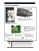
When installing DC cables:
Turn off DC circuit breakers before proceeding.
Battery positive (+) and negative (–) cables should be no longer than 10 feet (3 meters) each. This helps
to minimize voltage loss and other possible effects.
The modular construction of the GS8048A requires the use of two DC circuit breakers.
The cables for each overcurrent device must each be sized appropriately. Alternately, a single cable or
bus may be used if sized to the minimum total ampacity. The cables listed above are for each inverter in
a system. In a multiple-inverter system, each inverter requires its own cables and overcurrent devices of
the size indicated.
Install all overcurrent devices on the positive cable.
Tie, tape, or twist positive and negative cables together to reduce self–inductance. Run positive and
negative cables through the same knockouts and conduit.
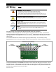
IMPORTANT:
Do not install hardware in a different order from the illustrations shown in Figure 16.
In all cases the battery cable lug must be the first item installed. It must make solid contact
with the surface.
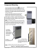
The Radian inverter has four battery cable terminals, two
positive and two negative. Each terminal is a threaded
hole which accepts a hex bolt (provided). Notes on
assembly and cabling are shown on the next page.
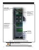
GS8048A
GS4048A