
Installation Guide


Installation
900-0160-01-01 Rev B
29
AC Wiring
WARNING: Shock Hazard
The neutral and ground conductors should be mechanically bonded.
Ensure there is no more than one AC neutral-ground bond at any time.
Local or national codes may require the bond to be made at the main panel only. The
GS Load Center (GSLC) is equipped with its own bond, which may need to be removed.
CAUTION: Equipment Damage
The Radian inverter cannot be connected to a three-phase source (utility grid or generator).
The L1 and L2 inputs cannot be connected to two lines of a three-phase power source.
IMPORTANT:
The installer is responsible for providing overcurrent protection. The AC input and output
must be protected with branch-rated circuit breakers of up to 50 Aac maximum size to meet
applicable code requirements.
NOTE:
The use of a GFCI-equipped AC source to power either the
G
RID
or
G
EN
input is not
recommended.
All system wiring must comply with national and local codes and regulations.
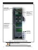
The Radian inverter/charger’s AC terminal block has nine positions for AC wires. The minimum
recommended wire size is #8 AWG (0.013 in
2
) or 10 mm
2
. Larger wire gauges may be required for
specific conditions. The largest size that can be used with the terminals is #6 AWG (0.021 in
2
) or
16 mm
2
wire.
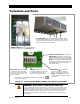
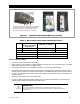
The inverter makes its AC connections using spring-loaded clamps. It is necessary to strip
approximately ½ inch (1.3 cm) of insulation from the end of each wire. Other tools are not required.
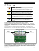
Figure 17 AC Terminals
The terminals labeled
L1
and
L2
G
RID
are used to connect to the two utility grid “hot” wires. The
L1
and
L2
wires are usually black and red respectively, and read 120 Vac each when measured with
respect to neutral. In a standard service,
L1
and
L2
are 180 degrees out of phase and should read
240 Vac when measured from one to the other.
Grid In
(L1, L2, Neutral)
Generator In (L1, L2, Neutral)
AC Out
(
L1
,
L2
,
Neutral
)