
Installation Guide


Installation
30
900-0160-01-01 Rev B
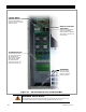
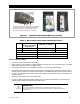
The
L1
and
L2
G
EN
terminals are used to connect to the “hot” wires on a 120/240 Vac generator.
Three neutral (
N
) terminals are available. These terminals are electrically common. Any of them
can be used to connect to neutral wires from various parts of the system. The most common
connections are to the neutral bus on the main panel or utility grid service, the neutral bus on the
output load panel, the neutral bus in the GSLC, and the neutral wire from a generator.
The Radian can accept input voltages that range between (nominal) 100/200 Vac and 120/240 Vac
(split-phase only). The range of input acceptance may need to be adjusted to the nominal voltage
of the system so that inappropriate voltages are not accepted.
The AC source(s) can power both battery charger and loads if sized correctly. Use the source
amperage and the charger size to determine actual maximum draw. Size the input circuit breakers
according to these specifications.
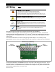
The terminals labeled
O
UT
are used to connect the Radian inverter to the load circuits. These
terminals also transfer power from an input source if it is available. (See the next page.) Size the
load circuit breakers accordingly.
A Ground Terminal Bus Bar (TBB) is also available if multiple ground connections are needed (see
Figure 14 on page 25).
WARNING: Shock Hazard
During an error shutdown, the inverter’s output terminals are not live. However, if the inverter
recovers from a shutdown, the terminals will become live without notice. Several error
shutdowns can be recovered automatically, including
Low Battery V
,
High Battery V
, and
Over Temperature.
See the Troubleshooting section and the list of error messages in the
Radian Series Inverter/Charger Operator’s Manual for more information.