
Installation Guide

Installation
900-0160-01-01 Rev B
33
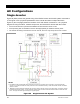
Accessory Wiring
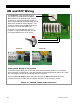
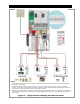
Figure 20 Accessory Connections
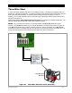
AUX Wiring
The Radian inverter has two sets of terminals which can respond to different criteria and control
many functions. These include cooling fans, vent fans, load diversion, fault alarms, and the
Advanced Generator Start (AGS) function.
The
12V
A
UX
terminals are a switched 12 Vdc power supply. They can supply up to 0.7 amps at 12
Vdc (8.4 watts). This is sufficient to drive a small fan or a relay controlling a larger device. The
terminals accept wire up to #14 AWG (0.0032 in²) or 2.5 mm². This circuit contains electronic
overcurrent protection, which resets after being overloaded. No additional fuses are required for
the
12V
A
UX
terminals.
The
R
ELAY
A
UX
terminals are “dry” relay contacts with no voltage. Their most common function is
to serve as a switch for the start circuit of an automatic generator using the generator control
functions. However, they can be programmed for other auxiliary functions as well. These terminals
can conduct up to 10 amps at up to 30 Vdc or 250 Vac.
CAUTION: Equipment Damage
This circuit has no overcurrent protection. A fuse of no larger than 10 amps must be
installed to protect the circuit. Since the internal circuitry of the
R
ELAY
A
UX
terminals does
not incorporate overcurrent protection, it is the responsibility of the installer to ensure the
circuit is protected. Internal failure that results from lack of protection is not covered
by the Radian warranty.
Each set of terminals has its own set of programmed criteria.
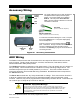
RTS cable
(RJ11, 4-conductor, telephone)
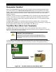
The upper board has ports for both the Remote
Temperature Sensor (RTS) and the system
display. The system display port is labeled
R
EMOTE
. The RTS port is labeled
B
ATTERY
T
EMP
. See the Operator’s Manual for functional
information on the RTS.
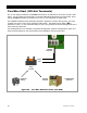
MATE3 or HUB cable
(RJ45, 8-conductor, CAT5 non-crossover)
System
Display
port
RTS
port
MATE
port
Additional
p
orts
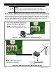
If a HUB Communications Manager is in use, it occupies
the inverter’s
R
EMOTE
port. The system display plugs
into the HUB product.
Inverters connect to communications manager
ports 1 and above. Charge controllers and other devices
connect to additional ports after the last inverter is
connected. See
Stacking
on page 40 for information on
connecting inverters.