
Installation Guide
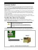

Installation
34
900-0160-01-01 Rev B
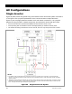
NOTE:
The menus for each set of terminals have identical options available, but can control
independent functions. For example, the
R
ELAY
A
UX
terminals can be used for generator
control, while the
12V
A
UX
terminals can simultaneously be used to control a vent fan in the
battery box.
The control logic for the
A
UX
output may be located in the inverter or it may be in the system display
or another location. Radian
A
UX
functions are located in the inverter and are described accordingly.
Although inverter-based functions require the system display for programming, they will function
even if it is removed. However, AGS programming is located within the system display even though
it uses the Radian
A
UX
terminals. It will not work if the display is removed. (Other devices may
also be able to control the terminals.) For generator control, see page 35.
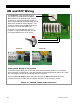
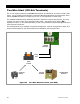
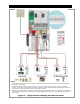
Figure 21 AUX Connections for Vent Fan (Example)
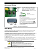
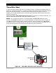
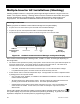
Figure 22 AUX Connections for Diversion (Example)
In this example, the
12V
A
UX
terminals directly
drive a 12-volt vent fan. The + and – wires on
the fan are connected to the
A
UX
terminals.
NOTE:
If another device is used, such as a
larger fan, it must not draw more than 0.7 amps.
Fan
Relay
Element
Turbine
NOTE: Relays and elements shown
are examples only and may vary
depending on the installation.