
Installation Guide
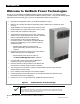
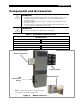

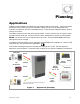

Table of Contents
4 900-0160-01-01 Rev B
List of Tables
Table 1 Components and Accessories ............................................................................................ 7
Table 2 Battery Bank Elements ...................................................................................................... 12
Table 3 Ground Conductor Size and Torque Requirements .......................................................... 25
Table 4 DC Conductor Size and Torque Requirements ................................................................. 27
Table 5 Changing Master Power Save Levels (GS8048A) ............................................................ 48
Table 6 Terms and Definitions ....................................................................................................... 55
List of Figures
Figure 1 Radian Series Inverter/Charger....................................................................................... 6
Figure 2 Radian Inverter and Accessories .................................................................................... 7
Figure 3 Applications (Example) ................................................................................................... 9
Figure 4 Bypass Switching .......................................................................................................... 15
Figure 5 Bypass Switching for Multiple Inverters ......................................................................... 15
Figure 6 Dimensions ................................................................................................................... 17
Figure 7 System Dimensions ...................................................................................................... 18
Figure 8 Installing the Mounting Plate ......................................................................................... 19
Figure 9 Mounting the Inverter .................................................................................................... 20
Figure 10 Mounting for System Components ................................................................................ 21
Figure 11 Removing the Front Cover ............................................................................................ 22
Figure 12 DC Terminals, Ribbon Cables, and Auxiliary Terminals ............................................... 23
Figure 13 AC Terminals, Ports, and Ground Bus .......................................................................... 24
Figure 14 Chassis Ground TBB .................................................................................................... 25
Figure 15 GS8048A and GS4048A Battery Terminals .................................................................. 27
Figure 16 DC Cable Hardware (Radian inverter) .......................................................................... 28
Figure 17 AC Terminals ................................................................................................................ 29
Figure 18 AC Sources ................................................................................................................... 31
Figure 19 ON/OFF Jumper and Connections ................................................................................ 32
Figure 20 Accessory Connections ................................................................................................. 33
Figure 21 AUX Connections for Vent Fan (Example) .................................................................... 34
Figure 22 AUX Connections for Diversion (Example) ................................................................... 34
Figure 23 Two-Wire Generator Start (Relay Aux) ......................................................................... 35
Figure 24 Two-Wire Generator Start (12V AUX) ........................................................................... 36
Figure 25
Three-Wire Generator Start (Example) ......................................................................... 37
Figure 26 Single-Inverter AC System ............................................................................................ 38
Figure 27 Single-Inverter AC Wiring with GS Load Center ........................................................... 39
Figure 28 OutBack Communications Manager and System Display ............................................. 40
Figure 29 Example of Parallel Stacking Arrangement (Three Inverters) ....................................... 43
Figure 30 Parallel Wiring ............................................................................................................... 44
Figure 31 Parallel Wiring with GSLC ............................................................................................. 45
Figure 32 Power Save Levels and Loads ...................................................................................... 46
Figure 33 GS8048A Power Save Priority ...................................................................................... 47
Figure 34 AC Test Points .............................................................................................................. 50
Figure 35 Grid Support Screens .................................................................................................... 53