
Installation Guide


Installation
900-0160-01-01 Rev B
43
Stacking Configurations
Parallel Stacking (Dual-Stack and Larger)
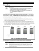
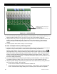
In parallel stacking, two or more inverters are stacked to create a single, common AC bus as shown
in Figure 29.
All inverters share a common input (AC source) on both L1 and L2. They run loads on common L1 and
L2 output buses. The master inverter provides the primary output. The slaves are connected to the
same L1 and L2 outputs and assist the master.
The slave outputs are controlled directly by the master and cannot operate independently.
Slave inverters can go into Silent mode when not in use. The master inverter will activate individual slave
inverters based on load demand. This reduces idle power consumption and improves system efficiency.
Up to ten inverters may be installed in a parallel arrangement. The example on this page shows three
inverters. The wiring diagrams on the next few pages show two.
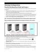
Figure 30 (see page 44) shows the general wiring of the inverters and the AC system connected to
them. This figure is not a physical representation of the inverters and does not depict the GSLC.
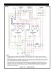
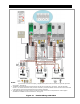
Figure 31 (see page 45) shows the locations of AC and network connections. This is a physical
diagram for wiring the GSLC, network components, and external AC devices with each inverter.
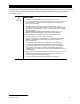
Figure 29 Example of Parallel Stacking Arrangement (Three Inverters)
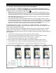
When installing a parallel system, the following rules must be observed.
Parallel stacking requires the system display and the communications manager. See the HUB10.3
literature for any required jumper configurations.
One inverter, and one inverter only, is always the master and is programmed as
Master
.
This is the default setting.
The master must be connected to port 1 of the communications manager. Other inverters must not be
assigned as master.
All slave inverters, regardless of number, should be assigned as
Slave
during programming. Slaves can
be connected to any port numbered 2 and above.
All wiring and circuit breakers must be sized appropriately for loads and inverter power.
The AC input (generator or utility grid) must be a split-phase source of the proper voltage and frequency.
The input/output bypass kit for the GS Load Center cannot be used. See page 14 for more information.
24 kVA
120/240 Vac
8 kVA
120/240 Vac
8 kVA
120/240 Vac
8 kVA
120/240 Vac