
Installation Guide


Installation
900-0160-01-01 Rev B
47
To set these items manually without the Profile Wizard:
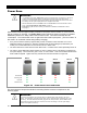
In the system display, the
Power Save Ranking
screen uses
Power Save Level
selections to
assign inverter ranks. The screen reads
Master Power Save Level
or
Slave Power Save Level
,
depending on the inverter’s stacking designation.
Master Power Save Level
appears on an inverter which is set as master (the default setting). When
stacking, this selection should only appear on the inverter using Port 1 of the communications manager.
The range of rank numbers is 0 to 31. The default value is 0. The master is normally left at this value.
Slave Power Save Level
appears on an inverter which is set as slave. The range of rank numbers is 1
to 31. (The default value for all ports is 1.)
The ranks are prioritized so that lower-numbered ranks turn on sooner and higher ranks turn on later.
The lowest-ranked unit will not go silent and will remain on unless ordered otherwise. The lowest-ranked
unit is expected to be the master. The priorities are the same across both screens; thus, if P01 (master)
is set at 0 and P02 (slave) is set at 1, the slave will turn on later. Since the
Master
item is the only one
that goes to 0, it is easy to ensure that all other units besides the master go silent.
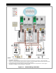
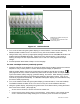
The GS8048A has two modules. The modules are controlled individually. The Power Save
function will activate one module at a time, making an additional 4 kW of power available for every
load increase of approximately 2.5 kW.
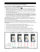
Figure 33 shows a system of four GS8048A inverters (the master and three slaves) in a parallel
system with a common load bus. The labels at the top indicate the ranking of each unit. The
notations at the bottom show how the units are activated in sequence as loads of approximately 2.5
kW are applied.
The first line shows little load and only the first module in Master is activated.
The second line shows load beginning to be applied. The second module in Master is activated.
The third line shows increasing load. The first module in Slave 1 is activated.
The fourth line shows even higher load. Slave 1 is completely activated.
In general, roughly 5 kW of loads are applied to fully activate an additional slave inverter.
In the example shown in Figure 33, an 8-kW load has been applied, fully activating the first slave.
In this example, loads of approximately 17 to 18 kW would be needed to turn on all inverters.
Figure 33 GS8048A Power Save Priority
Minimal Load On Off Off Off Off Off Off Off
approx. 2.5 kW (12 Aac)
On On Off Off Off Off Off Off
approx. 5 kW (24 Aac) On On On Off Off Off Off Off
approx. 7 to 8 kW (36 Aac) On On On On Off Off Off Off
Module 1 Module 2
Module 3 Module 4 Module 7 Module 8 Module 5 Module 6
Maste
r
Master Power Save = 0
Slave 1
Slave Power Save = 1
Slave 2
Slave Power Save = 2
Slave 3
Slave Power Save = 3