
Outback Radian AC Coupling Note

Application Note
©2019OutBackPower,Arlington,WA98223FB‐MM‐2/22/2019Page10of12
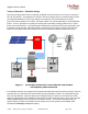
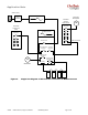
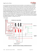
For the automatic method using the lockout relay, the generator L1 and L2 phases can be connected
to the G
EN IN bus bars, with the generator ground and neutral connected to their respective bus bars.
The L1 and L2 connections from the AC Gen In bus bars are then connected to the relay coil terminals.
The GTI L1 and L2 connections can be made to the 2PDT to the common relay contacts (pins 4 & 5)
as shown in Figure 8 and then the NC contacts (pins 3 & 7) are connected to the AC Output bus bars.
To automate the generator start using the OutBack MATE3s system display and controller, see
Advanced Generator Start (AGS) programming instructions in the MATE3s literature for specific steps
for setup. It is recommended to use the Voltage Start function with the appropriate low battery settings.
SOC start is normally disabled as the SOC accuracy can be off significantly when the batteries are not
being fully charged on a regular basis. Voltage Start should be more than adequate to keep the batteries
from getting discharged too deeply. Also, the Generator input mode should be selected for the Gen AC
Input Mode and Limits in the Inverter settings menu.
Figure 8 Generator Protection Relay and GTI Disconnect